13
❏
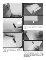
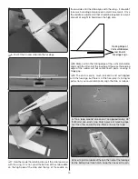
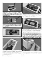
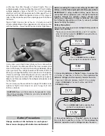
1. Tape a layer of 1/4" RC foam around your receiver battery.
❏
2. Some glow engine installations may require tail ballast,
so it is desirable to mount the battery as far back as practically
possible which is why the location illustrated in this manual
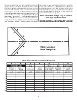
was chosen. Install the battery, then hold it into position
with pieces cut from the 1/4"x1/2"x 4" [4 x10 x100 mm] balsa
stick as shown.
Attach the Elevator and Rudder
❏
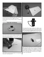
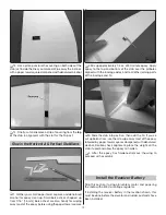
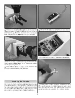
1. Cut the covering from the hinge slot in the end of the
fuselage and test-fi t a CA hinge. If the hinge fi ts too tight,
enlarge the slot a little with a hobby knife or a small razor
saw blade.
❏
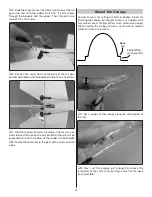
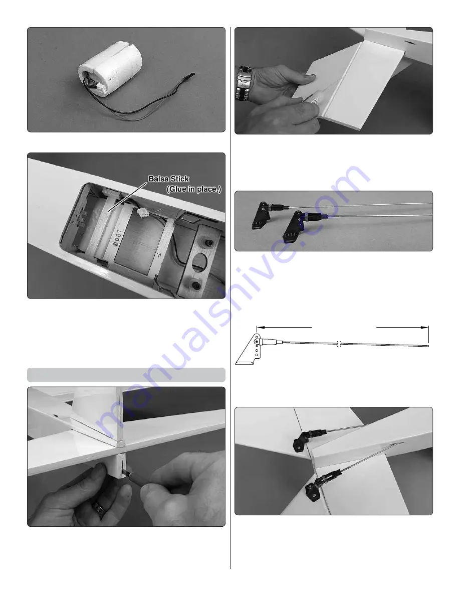
2. Applying the same procedures used for hinging the
ailerons to the wings, join the elevators to the stab with the
hinges and permanently glue them in with thin CA. (If you’ve
poked pinholes in one side of the covering over the elevators
be sure to put those sides down.)
❏
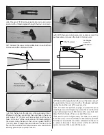
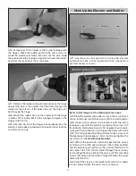
3. Make both elevator pushrods the same way you
made the aileron pushrods; thread the clevises onto two
27-3/4" [ 705 mm ] threaded one end pushrods, connect
the clevises with silicone retainers to the pushrods and
connect the clevises to the second-from-the-outer holes
in the control horns.
22-1/4" [ 570 mm ]
❏
4. Cut both pushrods to a length of 22-1/4" [ 570 mm ] from
the retainer screw to the end of the pushrod. Save one of
the pieces of wire you cut off.
❏
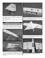
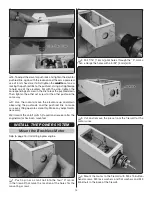
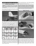
5. Insert the pushrods into the elevator guide tubes in the
fuselage and mount the horns to the elevators the same way
you did the aileron horns (drill 3/32" [ 2.4 mm] holes and use
M 2.5 x 15 wood screws and the horn back plates on the top
of the elevators).


