24
PREPARE THE MODEL FOR FLIGHT
Set the Control Throws
CAUTION:
If you’ve installed a brushless motor, the propeller
should not yet be installed. (Or remove the propeller
before turning on the radio and checking the throws on
the workbench.)
❏
1. It’s easiest to check and set the aileron throws with the
wing mounted to the fuselage. Install the wing and connect
the aileron servos to the receiver.
❏
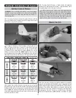
2. Support the back of the fuselage so the model will sit
level, or nearly level. Use a ruler (or a tool that measures
angular degrees) to measure and set the control throws
according to the measurements below.
Note:
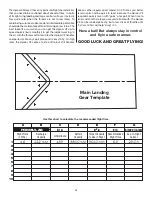
The control
throws are measured at the
widest part
of each surface
and the dimensions provided are for
each
direction of travel.
(Example: low-rate elevator throw is 7/8" up and 7/8" down.)
CONTROL SURFACE THROWS
(each direction)
A
IL
ERON
S
LOW RATE
7/8"
[22mm]
13°
Up & Down
1-1/2"
[38mm]
14.5°
Right & Left
5/8"
[16mm]
8.5°
Up & Down
E
LEV
A
T
O
R
S
RUDDER
HIGH RATE
1-1/2"
[38mm]
22.5°
Up & Down
2"
[51mm]
20°
Right & Left
1-1/4"
[32mm]
17.3°
Up & Down
3D
2-1/2"
[64mm]
40°
Up & Down
2-1/2"
[64mm]
25°
Right & Left
2-1/2"
[64mm]
36.5°
Up & Down
❏
3. Adjust the control throws as necessary by using the
programming in your transmitter and/or moving the pushrods
to holes farther out or in on your servo arms and/or the control
horns.
Note:
To achieve 3D throws the end points in your
transmitter programming will have to be set to maximum, or
near the maximum value.
❏
4. If using the 3D throws, a high volume of negative
exponential is desirable on 3D rates – approximately -60%
is a good place to start for each surface.
❏
5. While working with radio setup and programming
(and before the propeller has been mounted for brushless
setups), now would also be a good time to set the
fail safe
so that in the event the receiver ever loses signal the motor
will not turn. Follow the instructions that came with your
radio control system to set and check the failsafe.
Check the C.G.
❏
1. If you haven’t yet done so, get the model in completely
ready-to-fl y condition with the hatch covers, propeller, spinner
and muffl er (for glow engines) and LiPo battery (for brushless
setups). The spinner back plate may require reaming and
the spinner cone may require trimming to accommodate
the propeller; the fi rst “step” on a Great Planes Standard
Precision Prop Reamer (GPMQ5006) is suitable for glow

