5
❏
2.
Optional:
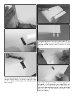
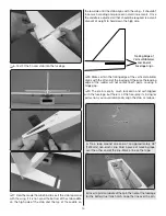
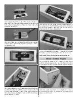
Three or four pinholes can be punctured
through the covering between each rib in the bottom of
the horizontal stabilizer, the elevators and ailerons, and in
one side of the vertical stabilizer and rudder. This will allow
heated, expanding air to escape while tightening covering.
These pinholes may appear obtrusive at fi rst, but when the
covering is heated they virtually disappear (plus, most of the
pinholes will be on the bottom). Heat the side of the covering
without the pinholes fi rst.
❏
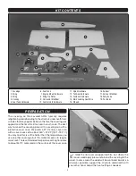
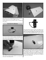
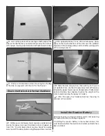
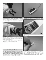
3. Stack a few paper towels on top of each other and cut
them into small squares. These small paper towel squares
come in handy for dabbing up excess CA or wiping up epoxy
when dampened with denatured alcohol.
❏
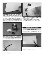
4.
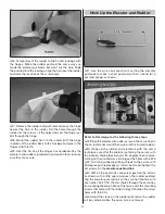
NOTE:
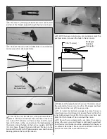
All machine-thread screws that thread into metal
(hex nuts, blind nuts, wheel collars, etc.) should be lightly
wetted with threadlocker.
❏
5.
NOTE:
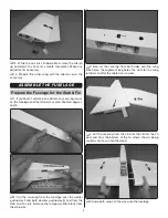
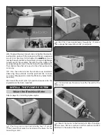
The procedure for preparing the holes in wood
for all wood screws is as follows:
A.
Drill the hole with the drill specifi ed in the step.
B.
Install, then remove the screw to “set” the threads.
C.
Add a drop or two of thin CA to harden the threads in
the hole.
D.
Allow the CA to harden, then install the screw(s) with
whatever it is that is being mounted/installed/attached
(servos, landing gear, etc.).
ASSEMBLE THE WING
Hinge the Ailerons
The left wing is shown in the images, but both wings could
be assembled simultaneously.
❏
1. If not yet done, separate the aileron from the left wing
and tighten the covering as previously described (the
pinhole
technique works well for the ailerons).


