background image

TC30
TRANQUILITY 
BURNER KIT 
INSTRUCTIONS

PART# TC30.NG04D
For TC30 Series D
Fireplaces

200317-24                                                                          TC30_NG04D                                                        5056.42904D

These instructions are supplementary to the Installation and 
Operating Instructions supplied with the fireplace and should be 
kept together. Refer to the  Installation and Operating Instructions for 
proper gas supply, safety requirements and operating instructions.

INSTALLER: Leave this manual with the appliance.
CONSUMER: Retain this manual for future reference.

Visit www.townandcountryfireplaces.net for the most recent version of this manual

Summary of Contents for TC30.NG04D

Page 1: ... and Operating Instructions supplied with the fireplace and should be kepttogether Refertothe InstallationandOperatingInstructionsfor proper gas supply safety requirements and operating instructions INSTALLER Leave this manual with the appliance CONSUMER Retain this manual for future reference Visit www townandcountryfireplaces net for the most recent version of this manual ...

Page 2: ...mbly including pilot gas lines B Panel base attached to burner assembly C Pebble assembly D Hardware tapered plugs screws brush panel clips E Side cover left hand side F 2 2 LBS SAND G Side cover right hand side A B C D E A F G Figure 1 TC30 Tranquility burner kit parts ...

Page 3: ...es in the bottom of the firebox with 1 2 screws as they are not required to attach this style of burner Figure 2 Figure 2 4 holes in fireplace floor to be plugged 2 Remove the 10 screws securing the access cover for the valve control center Figure 3 3 Bend the larger gas flex line the smaller gas pilot flex line and the ignition and sensor wires into shape Figure 4 so that the right hand side cove...

Page 4: ...ssembly 4 4 Place side covers between the burner tray and its base Figure 5 and Figure 6 before the burner tray is inserted into the firebox These will remain in the retracted position until later in the instal lation process 5 Position lower rear panel centered at the rear of the firebox Place burner assembly into the fire box against the rear panel Figure 7 ...

Page 5: ...or wires Bulkhead plate Figure 9 Ignition and sensor wires routing 6 Attach the main gas supply line and the pilot gas supply line to the bulk head fittings and tighten Figure 8 Ensure that there are no leaks 7 Feed the ignition and sensor wires through the bulkhead plate and gasket to the firebox Figure 9 ...

Page 6: ...gnition and sensor wires to the interface module as indicated in Figure 10 9 Once the gas and electrical lines are connected to the bulkhead and the interface module rein stall the valve control center s access cover Figure 3 on page 3 The panels are now ready to be installed Panel retainer Screw Screw Figure 11 Panel retainer location ...

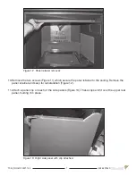
Page 7: ... retainer to the ceiling Remove the panel retainer and keep for reinstallation Figure 12 11 Attach a panel clip on each of the side panels Figure 13 These clips will fit over the upper rear panel holding it in place Figure 12 Panel retainer removal Figure 13 Right side panel with clip attached ...

Page 8: ... wall so that the upper rear panel can be slipped in behind the side panel 14 Install the upper rear panel Figure 15 Place one end on top of the lower rear panel and slip the side of the upper rear panel in behind the side panel Hold the upper rear panel up against the rear firebox wall until the retaining clip can be positioned over the top of the upper rear panel NOTE Remove this tag and plastic...

Page 9: ...Figure 16 and bend its retaining clip over the upper rear panel as in the previous step 16 Reinsert the two screws previously removed from the panel retainer but do not tighten Reinstall the panel retainer and fit slots to hook onto the two screws Tighten screws Figure 17 Figure 17 Panel retainer reinstalled ...

Page 10: ...crew holes in the side covers up with the screw holes in the burner tray base Use supplied self taping screws to secure the covers to the base Figure 18 18 Insert tapered plugs into raised burner ports to prevent sand from entering ports Figure 19 19 Place sand in tray Use supplied brush to spread and level the sand to just below the top of raised burner ports Gently blow excess sand from around p...

Page 11: ...orts 21 Remove pebble assembly from packaging by placing hand on top and tipping upside down Note that the rock in the lower left is hollow underneath and will fit over top of the pilot assembly Figure 21 22 Gently place pebble assembly onto sand base aligning 3 holes in the bottom of the rock set to the 3 pins located on the burner tray Figure 22 ...

Page 12: ...ocation pins Figure 22 Location pins for rock set Figure 23 Rock set in place Figure 24 Base panel Note The base panel Figure 24 is not used with the Tranquility burner and is a left over item 12 23 Install glass door Unit is ready for lighting ...

Page 13: ...he proper installation of this kit The installation is not proper and complete until the operation of the converted appliance is checked as speci fied in the manufacturer s instructions supplied with the kit CAUTION The gas supply and electrical power shall be shut off before proceeding with the conversion Note Factory supplied components must be used to ensure correct input After conversion confi...

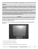
Page 14: ...ire white Interface module Figure 27 Disconnecting flame sensor and ignition wires at inter face module 4 Disconnect the pilot gas supply line at the bulkhead Figure 26 DO NOT disconnect the main gas supply line from the bulkhead 5 Disconnect the flame sensor wire and the ignition wire from the interface module Figure 27 and withdraw the wires back through the bulkhead plate and into the firebox a...

Page 15: ...the tray turn it on its side and lay it on its edge to expose the orifice and the pilot assembly Figure 29 Remove the pilot assembly bracket with its wires and pilot gas line attached while the burner kit is on its side See Figure 33 on page 16 8 Using a 1 2 wrench undo the natural gas burner orifice Figure 29 and replace with the pro pane gas orifice that comes with the conversion kit Figure 30 A...

Page 16: ...hutter screw Figure 31 open shutter half way and re tighten Figure 32 10 Remove the 2 screws holding the pilot assembly in place with a short screwdriver Figure 33 11 With a 7 16 wrench loosen the pilot head on the pilot assembly using a wrench to hold the bracket steady Figure 34 Figure 32 Air shutter half opened for propane gas ...

Page 17: ...s position Figure 36 shows the pilot in propane gas position 13 On the gas conversion label included in the conversion kit fill in the date and the name of the person who performed the conversion in the white area on the conversion label Peel off the pro tective backing and apply the conversion label directly onto the gas valve inside of the gas valve control center Figure 37 TC30 Propane gas conv...

Page 18: ...pressure requirement Supply Pressure Natural Gas Propane Min Pressure 5 0 WC 12 5 WC For purpose of input adjustment Max Pressure 13 9 WC 13 9 WC Manifold Pressure Maximum 3 5 WC 10 WC Minimum 1 6 WC 6 4 WC Gas Pressure Check 1 Remove the plug from the pressure test port The plug is located between the right side lintel and firebox side Figure 39 2 Thread the extension test fitting into the open p...

Page 19: ...appearance after the fireplace has reached operating temperature See Figure 42 for proper flame pattern Open primary air if the window glass and firebox have carbon accumulation and or the flames are long dark and stringy The shutter may also be opened to lessen the flame height NOTE Proper air shutter setting is required fully closed for natural gas and half open for propane The flame should be j...

Page 20: ...BLE 6 ORIFICE NG 32 7 PROPANE CONVERSION KIT not shown 8 SAND not shown 20 1 TRANQUILITY BURNER KIT TC30 NG04D 2 PEBBLE ASSEMBLY TC36 9499 3 MAIN SUPPLY TUBE 5019 223 4 PILOT TUBE 5019 225 WHEN ORDERING INCLUDE PART NUMBER WITH DESCRIPTION KIT CONTENTS NOT SHOWN Replacement Parts ITEM DESCRIPTION PART NO ITEM DESCRIPTION PART NO 5 PILOT ASSEMBLY CONVERTIBLE TCRP 5005025 6 ORIFICE NATURAL GAS 32 50...

Page 21: ...21 TC30_NG04D 200317 24 5056 42904D ...

Page 22: ...TC30_NG04D 200317 24 5056 42904D 22 ...

Page 23: ...23 TC30_NG04D 200317 24 5056 42904D ...

Page 24: ...ion adaptation or translation without prior written permission is prohibited except as allowed under the copyright laws For technical support please contact your retailer Web site www townandcountryfireplaces net 2975 Allenby Rd Duncan BC V9L 6V8 Printed in Canada ...

Reviews: