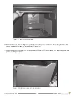
Figure 3: Access cover to valve control center.
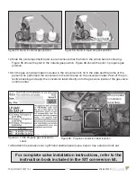
Figure 4: Flex line bent to shape.
3
TC30_NG04D 200317-24
5056.42904D
Tranquility Burner Installation
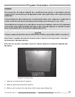
If converting to propane see conversion instructions on page 13 before proceeding with
Tranquility Burner Kit.
1. Plug the 4 vacant holes in the bottom of the firebox with 1/2” screws, as they are not required to
attach this style of burner (Figure 2).
Figure 2: 4 holes in fireplace floor to be plugged.
2. Remove the 10 screws securing the access cover for the valve control center (Figure 3).
3. Bend the larger gas flex line, the smaller gas pilot flex line and the ignition and sensor wires into
shape (Figure 4) so that the right hand side cover will fit over top of them before the burner is
placed into the firebox (Figure 6).


