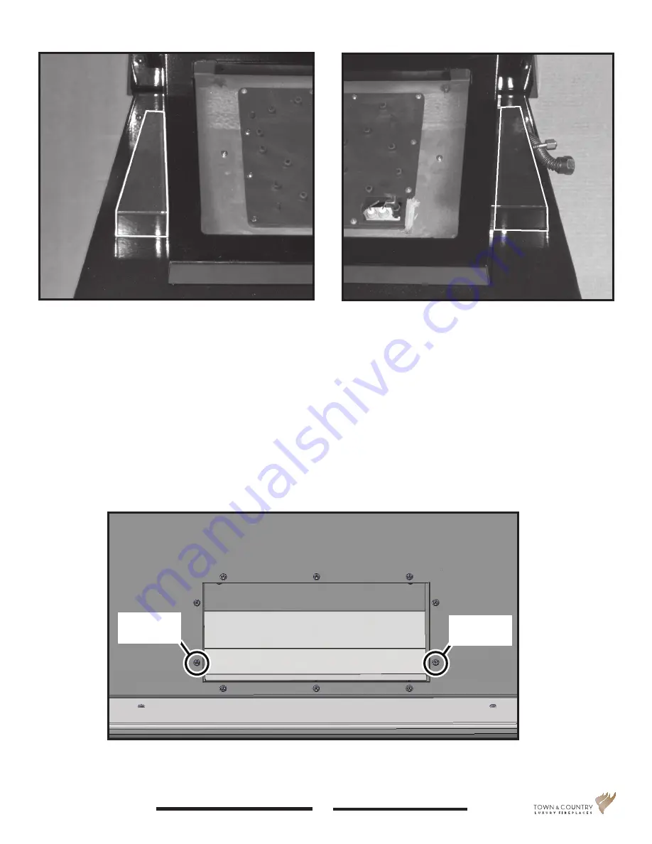
Figure 7: Left hand side cover.
Figure 8: Right hand side cover.
5
TC36_NG04D 240317-24
5056.427D4
6. Place side covers between the burner tray and its base (Figure 7 and Figure 8) before the burner
tray is inserted into the firebox. These will remain in the retracted position until later in the instal-
lation process.
7. Remove the two lower outside screws from the Air Channel as indicated in Figure 9. The lower
panel will be attached to the rear wall of the firebox using the two screws just removed.
Remove this
screw
Remove this
screw
Figure 9: Air channel.


