1
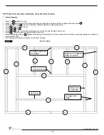
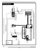
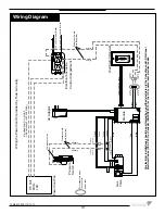
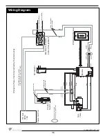
15 V
olt
60 Hz
1.8A
Power V
ent Fan
Pressure
Switch
AC Adaptor
Electrical box inside
Control Compartment
Gas
V
alve
Module
W
all Switch Receiver
Pull connectors apart
to connect to
power vent
White
Green
White
Orange
Black
Black
Black
Black
Red
120 V
olt Hot wire (Black)
120 V
olt Common wire (White)
1/4” Male
Connector
1/4” Male
Connector
1/4” Male
Connector
1/4” Male
Connector
1/4” Female
Connector
1/4” Female
Connector
1/4” Female
Connector
1/4” Female
Connector
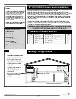
Wiring the Power V
ent Kit provided by
T
own & Country
Communication wires
Main
Pilot
Low pressure side
Orange
Orange
Pressure switch
wire (Supplied)
Power V
ent switch
wire (Supplied)
Black
Black
ST
ANDARD
A
WG 14-2 WIRE
OR EQUIV
ALENT
(NOT
SUPPLIED)
All electr
ical installations should be perf
or
med b
y
a qualifi
ed electr
ician t
o
the Canadian and U
.S.
National
Electr
ical Codes (CS
A C22.1 f
or Canada),
(ANSI/NFP
A 70 f
or the U
.S.) and/or local electr
ical codes.
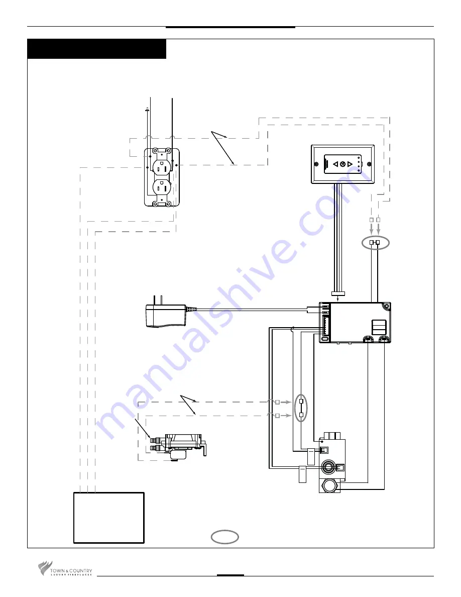
Wiring Diagram
26
TCWS.54CSTE 110712-72
Summary of Contents for TCWS54ST SERIES D
Page 70: ...70 TCWS 54CSTE 110712 72 ...

