VENT PIPE
This kit uses either Simpson
Duravent GS direct vent pipe,
Secure Vent direct vent pipe,
Selkirk Direct-temp vent pipe or
ICC Excel Direct vent pipe with a
5” inner pipe and an 8” outer pipe.
For part numbers see the table of
venting components on page 19 of
this manual.
Locate the fi replace as per the main instructions supplied.
Make the following modifi cations to add the components used with the Power Vent
kits. This kit can only be used in conjunction with the “B” & “C” series versions of
Town and Country Fireplaces. This installation must conform with local codes or, in
the absence of local codes, with the Natural Fuel Gas Code, ANSI Z223.1/NFPA 54,
or the Natural Gas and Propane Installation Code, CSA B149.1.
All electrical installation should be performed by a qualifi ed electrician to national
codes (CSA C22.1, ANSI/NFPA 70) and/or local electrical codes.
UNDER NO CIRCUMSTANCES SHALL A RHEOSTAT BE USED
TO ALTER THE VOLTAGE SUPPLY TO THIS UNIT.
ITEM PART
No.
DESCRIPTION
QTY
1
TCVT.502462
Power Vent Terminal
1
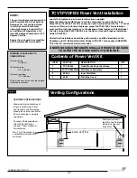
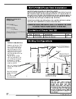
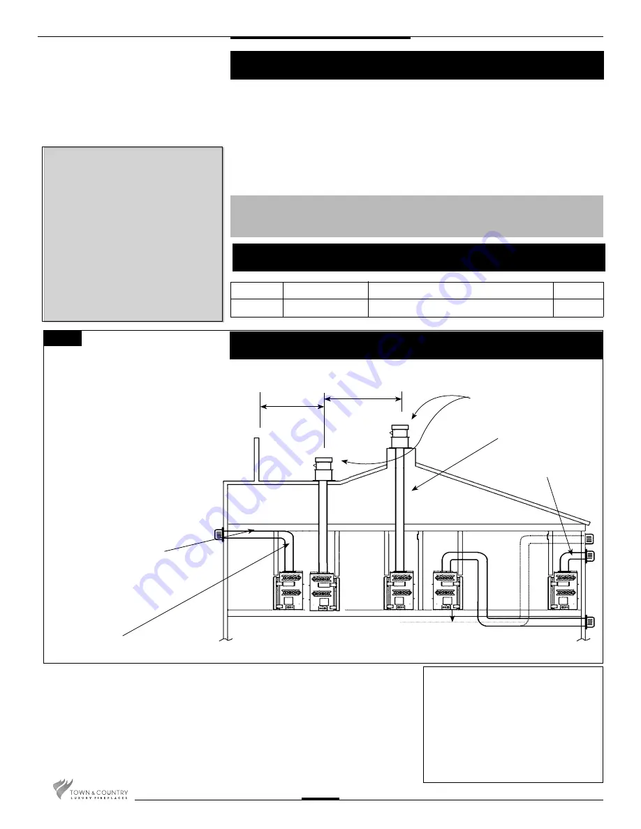
VENTING CONFIGURATIONS
Maximum vent length is 110 ft
plus six 90-degree elbows or
combination of other elbows
equaling 90-degrees, with a
maximum 66 foot vertical rise.
Minimum total vent length is
one 90-degree elbow plus one
foot horizontal.
The vent can be installed
with any combination of rise
and run between the fi gures
including up to 3 ft below
the unit. Ensure vent pipe is
properly supported.
Maximum Combined
vertical & horizontal
venting -
110 ft plus six
90-degree elbows.
Vertical Application must use TCVT.PVVCA Box in
conjunction with this kit
4 ft min.
6 ft min.
Max. 66 ft
Minimum total vent
length is one 90-degree
elbow plus one foot
3 ft below unit (Max) to
centerline of vent pipe
Fig. #51
Venting Confi gurations
TCVT.PVOB2 Power Vent Installation
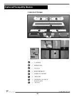
Contents of Power Vent Kit
Min. 1 3/4” Clearance to
combustible surfaces from
vent pipe.
MINIMUM CLEARANCES TO
COMBUSTIBLE
Vertical vent pipe:
1.75 in. (38mm)
Horizontal vent pipe:
1.75 in. (38mm)
All other clearances are as per the fi replace
installation instructions.
32
TCWS.54CSTE 110712-72
Summary of Contents for TCWS54ST SERIES D
Page 70: ...70 TCWS 54CSTE 110712 72 ...

