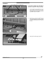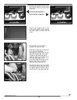
1. If installed, remove all media and the
burner tray.
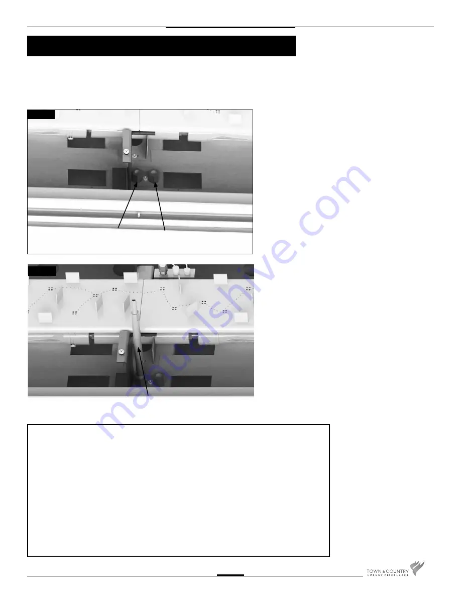
2.
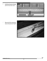
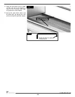
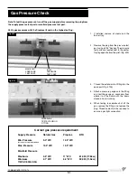
Remove the plug from the pressure test
port using a 3/16” hex key. The pressure
test ports are located next to the center
tray leg opposite from the pilot. (Fig. #99)
3.
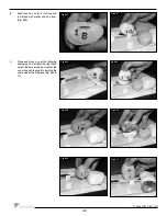
Thread the extension test fi tting into the
open port.(Fig. #100)
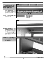
4.
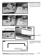
Attach a pressure gauge onto the fi tting
and rest the gauge on secondary fl oor
where it will be visible with the doors
closed and unit running.
5.
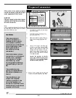
When testing is complete shut off the
gas, remove the fi tting and replace the
plug. Thread sealant will be required to
ensure a gas tight connection.
Note: To test the gas pressure, turn off the gas supply before removing the plug from
the supply pressure test port or manifold pressure test port.
Verify gas pressures with the fi replace lit and on the highest setting.
Correct gas pressure requirement:
Supply Pressure
Natural Gas
Propane
BTU
Min. Pressure
5.0" WC
12.5" WC
(For purpose of input adjustment)
Max. Pressure
13.9" WC
13.9" WC
Manifold
Pressure
Maximum
3.5" WC
11" WC
61,000 (17.8kw)
Minimum
2.1" WC
5.5" WC
39,000 (11.5kw)
115VAC 60Hz 8.5A
MANIFOLD
PRESSURE
TEST PORT
INLET
PRESSURE
TEST PORT
PRESSURE
TEST EXTENSION
FITTING
Fig #99
Fig #100
Gas Pressure Check
51
TCWS.54CSTE 110712-72
Summary of Contents for TCWS54ST SERIES D
Page 70: ...70 TCWS 54CSTE 110712 72 ...

