background image


www.toyorobot.com 


36 


5-2 Applying grease 


Make sure to turn off the power before proceeding the following. 

Apply the grease periodically. 

Recommended grease: AFEP2 or NSK LG-2 


If the unit is installed with the Toyo patented external grease fitting, which 

distributes to rail and ball screw if apply grease to the fitting. 


If the unit is without Toyo patented external grease fitting, please refer to 

below: 


a)


Remove top or side cover. 


b)


Apply grease directly to ball screw. 


Summary of Contents for Single Axis Series

Page 1: ...Installation Manual Toyo Single Axis Series www toyorobot com VER E 201401 ...

Page 2: ... 1 8 Adjustment and inspection 12 1 9 Repair and modification 13 2 Warranty 14 3 Part s Name 15 4 Installation 16 4 1 Transportation 16 4 2 Installation environment and base requirement 17 4 3 Driver motor assembly 18 4 4 Installation 28 5 Inspection and Maintenance 30 5 1 Inspection and maintenance frequency 31 5 2 Applying grease 33 5 3 Replacing and adjusting the dust proof plate 35 5 4 Consuma...

Page 3: ...ction may cause severe injury and serious threat endangering the life to the personals around the actuator DANGER Fail to follow the DANGER instruction will cause severe injury and serious threat endangering the life to the personals around the actuator CAUTION Fail to follow the WARNING instruction may cause severe injury to the personals around the actuator and the damage to the actuator or equi...

Page 4: ...s emergency stop when the door or panel is opened Install safeguards so that no entre is allowed except through the door or panel with safety interlocked equipped Stay outside of the safeguard during operation Activate emergency stop before entering the safeguard b Use caution to prevent hand or fingers from being caught by the moving parts WARNING Moving part may cause pinch or crush of hands and...

Page 5: ... axis actuator WARNING The vertical axis will slide down when brake are released and may cause hazardous situation Use a support to prop the vertical axis before releasing the break while emergency stop is activated Be careful not to get caught between the axis and the installing base when releasing the brake to perform direct teaching g Provide safety measure for end effector gripper WARNING End ...

Page 6: ...www toyorobot com 5 ...

Page 7: ...ut off the main power source to prevent possible electrical shock Never touch internal parts of a controller j Please consult with us before dealing with failure or malfunction of actuator WARNING Continue on using a failure or malfunctioned actuator may cause injury to the personals or further damage to the actuator or equipment please contact your TOYO s sales office or dealer for trouble shooti...

Page 8: ... m Electrical grounding WARNING Please ground the actuator and the controller to prevent electrostatics or electrical shock n Use correct parameter settings WARNING The actuator must be operated with correct tolerable moment of inertia and acceleration coefficients according to the manipulator tip mass and moment of inertia If these are not correct drive unit service life may end prematurely and d...

Page 9: ...d by mechanical stoppers WARNING Axis movement will not stop immediately after servo power supply is cut off by emergency stop or other safety functions d Brake for vertical axis An electromagnetic brake installation is essential on the vertical axis to prevent sliding down of the axis when servo power is cut off This brake shall be working when the controller is off or when the vertical axis serv...

Page 10: ...www toyorobot com 9 ...

Page 11: ...anger is more likely to occur from the automated systems instead of from actuator itself Thus appropriated safety measure must be taken on the part of the system manufacturer according to the individual system The system provider shall provide a proper instruction manual for safe and correct operating or service of the system ...

Page 12: ...f the electrical connection are correctly and properly wired If other connections such as pressured air supply or grounding connection proper If the actuator correctly connect to peripheral equipment Has the safety measure been taken If the installation location meet the specific environmental requirement c Check the following after turn on the controller from outside of the safeguard enclosure If...

Page 13: ...n 1 Soft limit settings please follow the precautions and procedures for each section 2 Teaching When performing teaching inside the safeguard enclosure comply with the instructions listed below 1 Before entering the safeguard enclosure Visual check if there is any hazard inside the safeguard enclosure Check that that programming unit MPB or DPB operate correctly Make sure there is no failure with...

Page 14: ...n case there are errors occurred After the automatic operation has started check the operation status and warning lamps to ensure that the actuator is in automatic operation Never enter the safeguard enclosure while automatic operation is active In case an error has occurred within the actuator or peripheral equipment obey the following procedure before entering the safeguard enclosure 1 Activate ...

Page 15: ...om 14 1 8 Adjustment and inspection Please do not attempt any installation adjustment inspection or maintenance of the actuator unless it is stated within this manual Please refer to the following chapters for details ...

Page 16: ...not attempt any repair part replacement or modification of the actuator unless it is stated within this manual The involved actions required qualified technician with professional knowledge and skills proceed without the knowledge and skills may result hazards ...

Page 17: ...nderbolts fire or any other natural or man made calamities Trouble caused by actions prohibited by this manual Modifications of the product not approved by TOYO or TOYO s sales representative Use of any other than genuine parts or specified lubricant or grease Insufficient or incorrect maintenance or inspection Repair or service done by non authorized dealer In addition we will be responsible for ...

Page 18: ...www toyorobot com 17 Motor end Motor Opposite Side Carriage Main Body Dust proof cover Side cover Top Cover Coupling cover 3 Part s Name 1 1 1 2 2 2 3 3 3 4 4 5 5 8 7 6 ...

Page 19: ...he ropes which can handle the weight Please also make sure the rope is properly positioned where the product is balanced while lifted In case transported by folk lifter or cart make sure the product is properly positioned to keep its balance and the parts which stands out of the folk or cart will not collide into any other objects The following parts of the actuator are not suitable part to apply ...

Page 20: ...gas or liquid Environment filled with flammable materials in any forms Locations where surrounded by electro magnetic disturbance statistic or radio wave emitting Locations where there are vibration sources nearby or easily collided Please provide enough space for service Installation base requirement Correct installation base Incorrect installation base a The installation base should be solid and...

Page 21: ...F from power source Assembled model ETH5 ETH6 Ball screw type actuator with direct driven externally assembled motor BC NO Explanation Explanation with pictures 1 Remove the 4 screws on the coupling cover 2 Loose the motor tightening screw on the coupling In case the coupling is not included please install one after removal of the coupling cover 3 Assemble the motor onto the actuator ...

Page 22: ...ot obstruct with surrounding objects upon installation Also please apply spring washers to the mounting screws Tightening the mounting screws 5 Tighten the tighten screws for motor on coupling 6 Screw back the coupling cover 7 Thus the assembly of direct driven externally assembled motor is finished ...

Page 23: ...or Motor on left side BL Motor on right side BR Motor on lower side BM NO Explanation Explanation with pictures 1 Dissemble the gear cover by removing the 4 mounting screws 2 Dissemble the position fixing plate from the unit for motor installation 3 The wrap around motor type required a belt and a screw on gear to drive the actuator ...

Page 24: ...e picture on the right is a bad example as there is no gap between gear and the motor 7 Install the motor with gears onto the unit with the position fixing plates in between and make sure there are spring washers installed on screws As belt tension adjustment is required please do not tighten the screws yet 8 Insert the belt on the gear which drives the ball screw first It is usually firstly inser...

Page 25: ...djust the tension of the belt by turning the screw with the open wrench 11 After the tension of the belt has met the requirement tighten the mounting screws of the motor 12 Fix the nod on the tension adjustment screw 13 Use a belt tension gauge to confirm if the belt tension is correct Please refer to Table 1 Ball screw type actuator belt tension meter ...

Page 26: ...ET C H 5M 2GT 12W 196L 10 15N ET C H 6 3GT 12W 207L 10 15N ET C H 6M 2GT 12W 196L 10 15N ET C H 10 BL 3GT 15W 336L BR 3GT 15W 252L BM 3GT 15W 273L 46 56N ET C H 12 BL BR 3GT 15W 300L BM 3GT 15W 273L 46 56N ETH 13 BL BR 5GT 15W 340L BM 5GT 15W 275L 55 65N ET C H 14 BL BR 5GT 15W 340L BM 5GT 15W 275L 55 65N ET C H 17 BL BR 5GT 20W 420L BM 5GT 20W 340L 95 105N ET C H 22 BL BR 5GT 20W L475 BM 5GT 20W ...

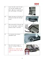
Page 27: ... ETB14 ETB17 ETB22 Belt type actuator NO Explanation Explanation with pictures 1 Remove the screws for motor mounting 2 Dissemble the gear cover by removing the 2 mounting screws 3 The required components for motor installation are motor belt and gear ...

Page 28: ...he gear is installed on the motor there is a small gap between gear and motor 6 The picture on the right is a bad example as there is no gap between gear and the motor 7 Tighten the two screws to fix the position of the gear 8 Install the motor and gear onto the unit Make sure there are spring washers installed on screws and also the position of the power outlet of the motor meet the requirement ...

Page 29: ...grip first In this case it s the motor side one 11 Install the belt onto both gear 12 Adjust the tension of the belt by moving the motor mounting plate once the belt reach the correct tension please tighten the screws for motor mounting plate 13 Use a belt tension gauge to confirm if the belt tension is correct Please refer to Table 2 belt type actuator belt tension meter ...

Page 30: ...www toyorobot com 29 14 Re assemble the gear cover to finish the assembly of the motor ...

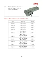
Page 31: ...ning belt spec Tension Belt spec Tension ET C B 5 2GT 9W 25 2N ET C B 6 2GT 12W 34 5N ET C0B 10 AT5 15W 96N 1000mm 5GT 15W 260L 96N ET C B 14M AT5 22W 157N 1000mm 3GT 25W 288L 123N ET C B17M AT5 30W 220N 1000mm 3GT 25W 288L 123N ET C B 22M AT5 50W 373N 1000mm 5GT 30W 430L 220N ...

Page 32: ...as follow a Check screw position on installation surface matches the ones on unit please refer to the specification sheet b Remove the side cover or the top cover of the unit c Move the carriage to ensure all screws are installed d Tighten all screws to install the unit ...

Page 33: ...m 32 e Install the covers back to finish installation Please note that for ET C H5M and ET C H6M the removal for dust proof plate is required please refer to 5 3 Replacing and adjusting the dust proof plate for details ...

Page 34: ...e proceed as follow Daily inspections before operation Everyday Seasonal inspection and maintenance Every three months Semi annual inspection and maintenance Every six months Annual inspection and maintenance Every twelve months More frequent inspection and maintenance are required with more frequent operation 1 5 Inspection and Maintenance ...

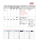
Page 35: ... there are dirt on the rail remove and re apply grease Make sure there are enough grease on the parts Dust proof plate Check if there is any damage Check if it is loose Replacement is required if it effects functionality Re adjust the plate if any part of it is loose Linear rail Check if the screw fixing the rails has gone loose Please refer to Table 3 various parts of screw torque values chart Ch...

Page 36: ...hart Tighten if loose Nut Recommended grease AFEP2 or NSK LG 2 Slides Check if there are noises while slide is moving Recommended grease AFEP2 or NSK LG 2 If there are dirt on the rail remove and re apply grease Make sure there are enough grease on the parts Table 3 various parts of screw torque values chart Screw Size Torque value kgf cm Torque value N m M3 15 1 5 M4 37 3 7 M5 72 7 2 M6 118 11 8 ...

Page 37: ...lly Recommended grease AFEP2 or NSK LG 2 If the unit is installed with the Toyo patented external grease fitting which distributes to rail and ball screw if apply grease to the fitting If the unit is without Toyo patented external grease fitting please refer to below a Remove top or side cover b Apply grease directly to ball screw ...

Page 38: ...www toyorobot com 37 c Apply grease directly to linear rail d Apply grease to sliders via greasing fitting on slider e Apply grease to nut via greasing fitting on nut ...

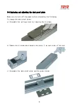
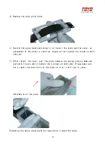
Page 39: ...e sure to turn off the power before proceeding the following To change the dust proof plate a Dissemble the carriage cover by removing the 4 screws b Remove the 4 screws which mounts the plate 2 at each sides of the unit c Dissemble the dust proof plate and the plate holder ...

Page 40: ...ed please do not tighten the screws on both ends yet f After install the cover pull the plate towards the end by pushing down and push with fingers while tighten the 4 screws at both ends Please make sure not to apply too much force on the plate or else it will easily cause deformation of the plate Repeating the above steps might be required to tighten the plate ...

Page 41: ...te Make sure to turn off the power before proceeding a Loose but not removing the mounting screws at both end of the plate b Pull the plate towards the end by pushing down and push with fingers while tighten the 4 screws at both ends Please make sure not to apply too much force on the plate or else it will easily cause deformation of the plate ...

Page 42: ...ged consumed after certain period of time of operating please check the status of the following parts during maintenance Parts Replacement required when Sensor No longer functional Dust proof plate Expended too much or damaged can be checked visually Belt Broken or ripped ...

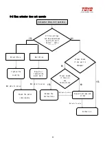
Page 43: ...e setting of the motor for rigidity If the ball screw are greased If the linear rails are greased Apply Grease Visual check if the slides are shifted Adjust carriage and slides Contact us Link NO NO NO NO NO NO YES YES YES YES YES YES Not able to solve Not able to solve If the parameter meet the spec Payload RPM acceleration Apply Grease Noise Check if the carriage is stuck after release of the br...

Page 44: ...Check if the coupling is loose Check the setting of the motor for rigidity Motor belt been too tight or too loose please refer to the belt tension table to adjust Contact us Tighten the coupling replacement is required if failed YES NO YES NO Not able to solve Not able to solve Not able to solve ...

Page 45: ...eplace the motor belt If the carriage can be pushed back and forth with motors cable unplugged Visual check if any part is damaged Adjust carriage and slides Contact us YES YES NO NO Tighten the coupling Visual check if there is any obstructions NO Remove the obstructions YES Not able to solve Not able to solve Not able to solve Not able to solve ...

Page 46: ...omation Co Ltd Add 50 YongKe Round Rd Yongkang Dist Tainan City 710 Taiwan TEL 886 6 2021347 FAX 886 6 2025974 WEB http www toyorobot com EMAIL toyo sales msa hinet net The content is subject to change without notice C copyright owned by Toyo Automation Co Ltd ...

Reviews: