DS4-2499D
- 4 -
4. Major Specifications
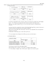
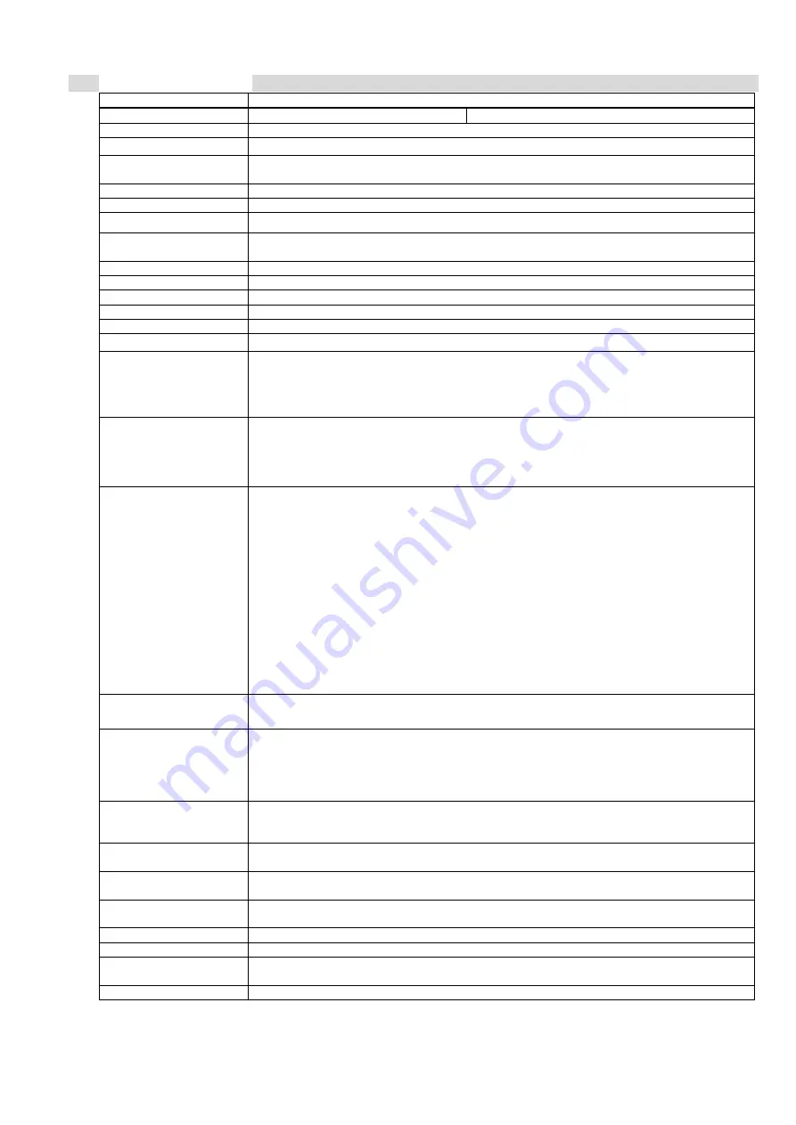
Item Specification
Model SOT-EQ80A
SOT-EQ80B
Environment
IEEE802.3(Ethernet)
Transmission rate
Cable side 10 Mbps
(effective throughput 2Mbps max.)
Power voltage
Rated voltage: 24VDC Power ripples 10% or less
Voltage: 18 - 30VDC Peak voltage including ripples: Within 30V
Consumption current
Less than 150 mA (at 24 VDC input)
Interface
10BASE-T (Auto negotiation, AutoMDIX compatible)
Transmission method
Full-duplex, bi-directional
Communication control
method
Store & forward, flow control (IEEE802.3x, back pressure)
Connected to:
Network card or switching hub
Transmission distance 0.2-80m
Directivity
1 degrees
Modulation method
FSK
Lighting element
Near infrared light emitting diode (light emitting wavelength 870 nm)
Receiving element
PIN photodiodes
Auxiliary output
DL: “ON” when communication is permitted
ALM: “OFF” when the reception level is low
Photo coupler insulated NPN open collector outputs
Output rating: 30VDC 50mA MAX
Connection
For signal: RJ-45 modular jack
Up to category 3 or more twist pair cable 100 m
Automatic switching between straight/crossing cables by means of
AutoMDIX
For power/aux. output: 5-polar connector terminal block (Phoenix MSTB2.5/5-GF-5.08)
Indicators
POW: Power indicator lamp (red); Shows red when power supply is on
LINK: Link indicator lamp (green); Shows green when Ethernet is connected normally
SD: Sending data indicator lamp (red); Shows red when sending data input is on.
RD: Receiving data indicator lamp (green); Shows green when received data output is
on.
FDX: Full-duplex indicator lamp (red); Shows red in full-duplex connection.
Own unit CD: Clear data indicator lamp (red); Shows red at a sufficient reception level
of own station for communication.
Own unit LEVEL: Reception level indicator lamp (4 points) (green); Shows green
according to own station reception level.
Receiving unit CD: Clear data indicator lamp (red); Shows red at a sufficient reception
level of receiving unit for communication.
Receiving unit LEVEL: Reception level indicator lamp (4 points) (green); Shows green
according to receiving unit reception level.
CH: Channel indicator lamp (red); Shows red when CH2 is selected.
Check terminals
DC voltage corresponding to the reception level is provided.
(Use the DC voltage range with a 10k
Ω
/V or higher tester.)
Setting switches
4-pin dip switch
SW1: Auto negotiation ON/OFF
SW2: Communication mode full-duplex/half duplex
SW3: 10BASE-T link ON/OFF in light shielding
SW4: Used for switching between CH1 and CH2
Operating ambient
illumination
Solar beam: 10,000 lx or less
Fluorescent, incandescent lamps: 3,000 lx or less
No externally disturbed light shall directly enter the receiver.
Operating ambient
temperature
–10 - +55°C No freezing allowed
Operating ambient
humidity
10 - 85% RH No condensation allowed
Resistance to vibration
Frequency: 10 - 55 Hz, complex amplitude: 1.5 mm, sweep: 5 min
20 cycles in each of X, Y and Z directions (per JIS C0040)
Resistance to impact
500 m/s
2
10 times in each of X, Y and Z directions (per JIS C0041)
Protection class
IP40
Outside dimensions
(weight)
See Outside Drawing (weight 350 g).
Accessories
Fixture (1 set), screws for fixture (4 pcs), power/aux. output plug (1 pc)


