- -
69
1K
1K
+12V
+5V
-5V
BT136
270
270
473
270
1¦ÌF450V
CPU9 foot
N wire
L wire
CPU10 foot
R
S
C
L
N
N
L
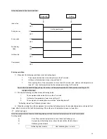
Wiring diagram
for compressor
outdoor fan motor
①
Stepping motor is, in reality, a four-phrase motor, the processor outputs four different phases
of pulse signals to enable the motor turn, meanwhile control the turning speed;
②
Pulse signals are output through the four feet of CPU 23.24.25.26,then their directions are
reversed by IC 2003 device to control the turning speed and turning angle of the stepping
motor.
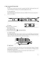
2.6 PG motor:
PG motor is used as indoor fan motor. its work principle is as follows:
1) The circuit, comprised by Q1, D5, D6, R1, R2 triodes, produces pulses, which are sent to CPU for further
processing. Then the processed pulses are used to control the turning speed of PG motor.;
2) There are HALL elements inside the PG motor. Each round the motor turns, the hall elements will be sensitized to
produce three pulses, which will be fedback to CPU to form a feedback circuit, so as to stabilize the turning speed.
3) The optical coupling comb
ination drives the controllable silicon circuit, which is showed as the below diagram:
2.7 Electric control section with powerful electricity.
The section that is in front of the transformer is powerful electricity section, which must be handled with care when
doing the repairing.
The CPU drives 2003,2003 drives the relay, the relay drives the compressor.
3. Function of all the elements and identification of the failures
3.1 Function of the different CPU feet:
Foot1,2 .for transistor vibrator; Foot 3.for grounding; Foot 4.for room temperature sensor; Foot 5.for indoor coil
temp. sensor ; Foot 6 for outdoor coil temp. sensor ; Foot 7 for selection; Foot 8 for grounding; Foot 9 for PG
driving; Foot 10 for PG feedback; Foot 11 emergency switch; Foot 12 for ; Foot 13 for signal receiver; Foot 14 for
economical lamp; Foot 15 for powerful lamp; Foot 16 for timing lamp; Foot 18 for operation lamp; Foot 19 for
four-way valve; Foot 20 for outdoor fan motor; Foot 21 for compressor; Foot 22 for buzzer; Foot 23 for stepping
motor 4; Foot 24 for stepping motor 3; Foot 25 for stepping motor 2; Foot 26 for stepping motor 1; Foot 27 for reset;


