138
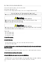
5. Remove the joint of two connectors between the control board
<VFC66R-Z> and the optional board.
・
Push up the knob to remove the joint of the connectors.
6. Push four claws of the support holding the optional board
into the support.
・
The support fixes the optional board to the chassis of the
converter.
・
When having a difficulty in pushing the claws, use a
needle-nose plier.
7. Remove the optional board.
8. Remove the flat cable of the control board <VFC66R-Z>.
9. Push four claws of the support holding the control board <VFC66R-Z> into the support.
・
The control board <VFC66R-Z> is also fixed to the chassis of the converter with the support.
・
When having a difficulty in pushing the claws, use a needle-nose plier.
10. Remove the control board <VFC66R-Z>.
11. Align four holes on a new control board <VFC66R-Z> to the support.
12. Push the control board <VFC66R-Z> until the claws of the support hang on the upper portion of the board.
13. Align the four holes on the removed optional board to the support.
14. Push the optional board until the claws of the support hang on the upper portion of the board.
15. Connect the flat cable of the control board <VFC66R-Z>.
16. Push up the knobs of the connectors [CN1] and [CN2] on the optional board.
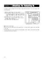
Optional board
Control board
Claw
Knob
Optional board


