150
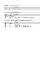
11.6.
Area F (protection function/traceback setting area)
Display
Contents
VF64R
VF66R
F-00
F-00
Overload protection setting
F-01
F-01
FCL level setting
F-02
F-08
Traceback_pitch
F-03
F-09
Traceback_trigger_point
F-04 through
15
F-10 through
21
Traceback CH1 through 12 selection
11.7.
Area G (setting area for analog input and output)
Display
Contents
VF64R
VF66R
G-00
L-9, 11
Analog input positive side adjustment gain: VF64R/
analog input (2), (3) gain: VF66R
G-01
L-9, 11
Analog input negative side adjustment gain: VF64R/
analog input (2), (3) gain: VF66R
G-02
L-07
Analog input characteristics selection: VF64R/
analog input (2), (3) characteristics selection: VF66R
G-03
-
Analog input zero limit: VF64R
G-04
L-10, 12
Analog input offset adjustment amount: VF64R/
analog input (2) offset: VF66R
G-05
L-01
Analog output selection: VF64R/
analog output (2) selection: VF66R
G-06
L-03
Analog output adjustment gain: VF64R/
analog output (2) gain: VF66R
G-07
L-04
Analog output adjustment offset: VF64R/
analog output (2) offset: VF66R
G-08
L-02
Analog output 2 selection: VF64R/
analog output (3) selection: VF66R
G-09
L-05
Analog output 2 adjustment gain: VF64R/
analog output (3) gain: VF66R
G-10
L-06
Analog output 2 adjustment offset: VF64R/
analog output (3) offset: VF66R
G-11
-
Insulated analog input adjustment gain: VF64R
G-12
-
Insulated analog input offset adjustment amount: VF64R
Analog input/output
●
The analog input/output terminal configuration varies by the product series.
Set the parameters with reference to {5.3.3. Area b} and {5.3.10. Area L}.
11.8.
Area J (communication option setting area)
Options vary by the product series.
Set the parameters with reference to {5.3.9. Area J}.

