21
3.3.
How to Connect Converter
3.3.1.
How to Connect Converter Terminals
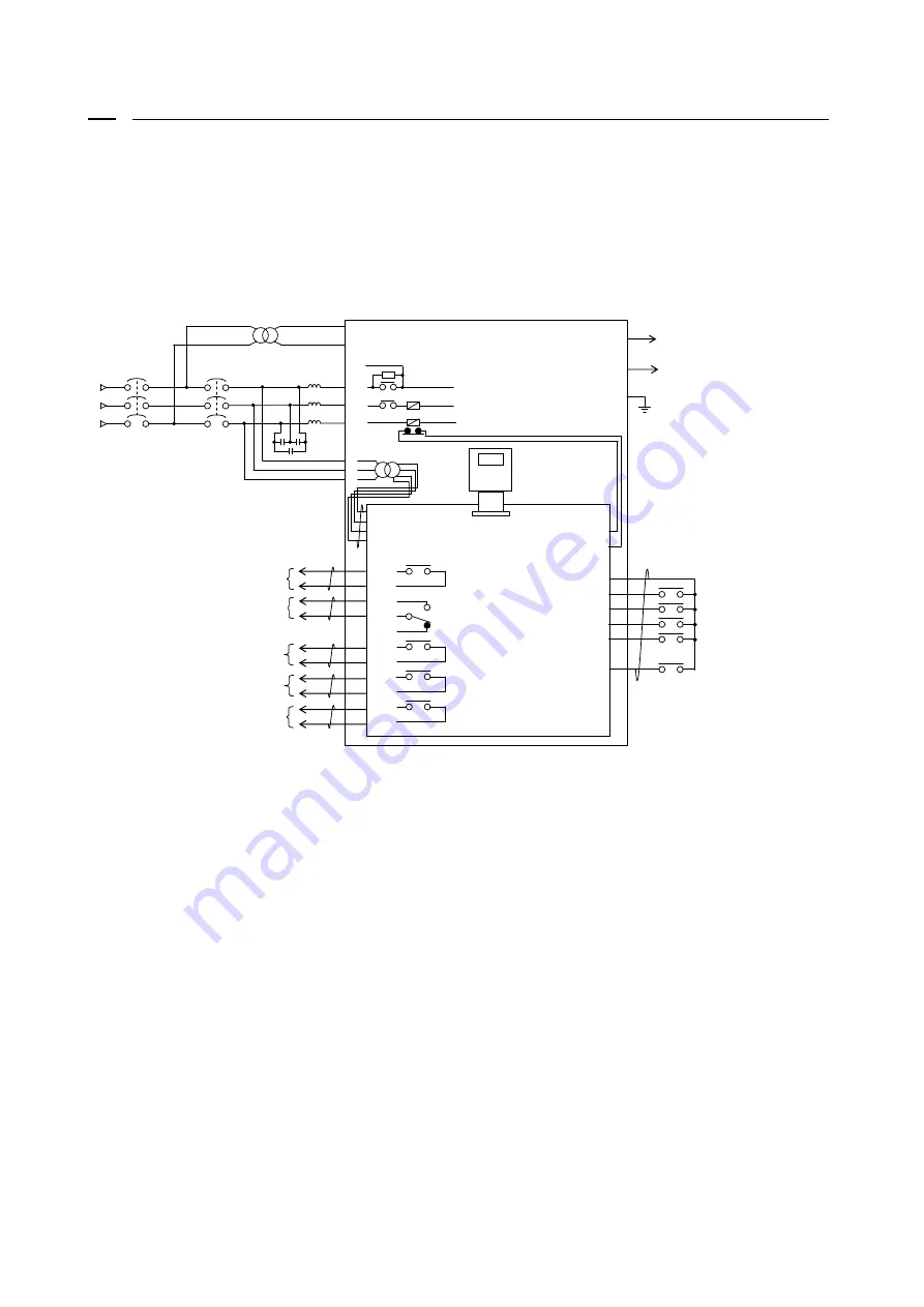
The figure below shows the connection diagram of the converter (VF66R-7522,9022, and 7544 through 31544)
terminals.
For specifications of each terminal, refer to {3.4. Terminal Specifications}.
(1) Input the specified input voltage. Inputting 400 V to the 200 V class converter damages the unit and causes
a very dangerous situation.
(2) Be sure to connect MCCB of appropriate capacity to the main circuit input side.
(3) Be sure to connect the power supply line to RA, SA and TA. Connect so that the main circuit terminals [L1/R],
[L2/S] and [L3/T] correspond to RA, SA and TA, respectively.
(4) Be sure to connect to the ground terminal for safety reasons.
(5) To connect five or more inverters between the converter outputs of [+] and [-], you may need to connect
an adjustment resistor between the RR and R terminals. In this case, contact us.
(6) The AC power supply terminals [MR] and [MT] for the control circuit are not connected to the power supply
in normal situations. Connect them when the control circuit power needs to be turned on after turning off
the main circuit power. Be sure to insulate from the main circuits of [L1/R], [L2/S] and [L3/T] using a
transformer.
When the control power supply terminals [MR] and [MT] are used in parallel models (VF66R-15022, 18022,
and 40044 through 100044), power should be supplied to not only a master unit but a slave unit.
(7) The AC reactor used in the PWM sine wave mode is different from that used in the 120-degree conduction mode.
Be sure to use the AC reactors specified by Toyo Denki.
52MA
VFC66R-Z
TB1
GND
86A
CN2
SET66-Z
L1/R
L2/S
L3/T
-
+
運転
故障保護
運転
(START)
多機能入力
PWM
正弦波コンバータモード
(予備)
非常停止
(EX_F)
リセット
(RESET)
MCCB
200
~
230V
380
~
460V
50/60Hz
TB1
4INC
4STA
4I
CN8
Fuse(
+
)
Fuse(
-
)
PS
START
MI5
MI4
MI1
MI2
MI3
インバータ運転可
4ATAa
4STAc
4Ic
4Ia
4INCa
4INCc
86Ab
86Ac
86Aa
52MAa
F
52M
絶縁トランス
RR
52MAc
RA
SA
TA
MR
MS
MT
1
2
3
4
VF66R
AC
リアクトル
C
MC ON
MC ON
中
TB1
E
Insulation transformer
AC reactor
Operation
Failure protection
Inverter operation enable
During MC ON
Converter operation
contact
AC fuse cut
DC output
Operation(START)
Reset(RESET)
Emergency stop(EX_F)
Multifunction input
(Unavailable)
PWM sine wave mode
Converter operation
contact
MC ON


