13
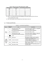
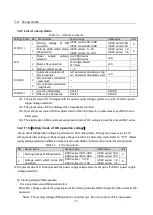
Table 3.1 Main circuit used cable (DB usage rate 10%ED
Main current[A]
Wiring size[mm
2
]
Number of times to twist[turn/m]
200
38
5
160
22
7
110
14
8
80
8
10
50
8
10
40
5.5
10
30
3.5
10
18
2
10
※
Table 3.1 is the wire size at the time of adopting the fire-resistant poly flex time electric wire.
( Example:MLFC[Hitachi Cable])
※
Twist a wire equally so that the length of each wire becomes the same.
3.3
Terminal specifications
Table 3.2 List of terminal specification
Device
Terminal
number
Use
Description
Main
circuit
P
DC voltage input (+ side)
For DBR connection
For thermal relay (OCRY) connection
Connect the inverter-middle D.C. voltage(
○
2
)
Connect a braking resistor
Connect the thermal relay(OCRY)
PR
For DBR connection
Connect a braking resistor
N
DC voltage input (- side)
For thermal relay (OCRY) connection
Connect the inverter-middle D.C. voltage
(
○
)
Connect the thermal relay(OCRY)
Earth
Connect the ground
VFDB
2009-Z
terminal
block
TB2
DB-IN
Slave input
DB operation will be started if a signal is
inputted during DB operation permission.
DB-ON
master instructions
A signal is outputted when the
inverter-middle D.C. voltage exceeds DB
operation starting potential (F10).
86A
Protection contact
DB unit turns on during the protection mode.
(86A
:
AC230V
0.5A)
52MA
Operation contact
It will be in the state in which DB operation is
possible by ON.
Summary of Contents for VFDB2009 Series
Page 1: ...VFDB2009 Operation Manual...


