24
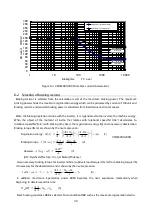
supply voltage of an inverter.
Note.2) When you use regeneration stall prevention function of an inverter, please give the starting
voltage of DB operation, and regeneration stall prevention voltage of an inverter as the same
voltage value. Refer to the inverter instructions manual of our company for details.
Note.3) At the time of communication option PC board [DBIF2009-Z] use, DB operation starting
voltage preset value of VF66 series inverter is set automatically. Refer to "7.1.1 Extention of
the function by appling of a communucation option PC board" for details.
○
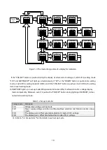
Voltage width which stops DB operation
It is a parameter about DB operation stop.
After DB operation start, if D.C. voltage falls only DB operation stop voltage width from DB operation
starting voltage, DB operation will stop.
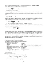
DB operation stop voltage
=
DB operation starting voltage
DB operation stop voltage width
Ex When DB operation starting voltage was set as 720V and DB operation stop voltage width is set as 36V
DB operation is started when the D.C. voltage of an inverter becomes more than 720V. After DB
operation start, when D.C.voltage falls or more 36 V from 720V, DB operation is stopped.
5.4.3
F20
Power supply voltage selection
・
Master / Slave selection
・
Station number set-up mode
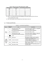
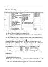
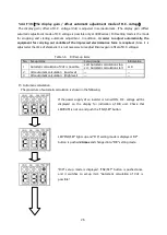
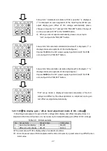
In F20 set-up mode, a setup of a power supply voltage series, a setup of single or Master/Slave sysytem,
and a setup of station number are performed.
Table 5.6
F20 set-up items
No.
Set-up items
Set-up range
Initial value
1
Power supply voltage selection
Ac2:200V series
Ac4:400V series
Ac4
2
Master / Slave selection
cF0:Single/Master
cF1:Slave
cF0
3
Station number set-up
(
※
)
1
~
7
1
※
No.3: Station number setup is set up when using communucation opution [DBIF2009-Z]. When not
using DBIF2009-Z, it is not necessary to set up.
○
Power supply voltage selection
Set up in accordance with the power supply voltage series of the inverter to be used. Moreover, it is
necessary to switch the connector on VFDB2009-Z PC board to compensate for this setup. Refer to
"5.2.1 Change of power supply voltage" for details.
○
Master / Slave selection
Change a setup according to single or parallel operation of DB unit. In using it by connection of figure
3.3 only in VFDB2009 series, it sets a setup to "cF0." When operating by parallel of the same connection
as VFDB2002, or when operating by parallel with VFDB2002 and VFDB2009, one set is made into
Master unit and other units are set as Slave unit.
Summary of Contents for VFDB2009 Series
Page 1: ...VFDB2009 Operation Manual...

