A56704
Seal Width
4 to 7 mm
B
A
A
B
(0.16 to 0.28 in.)
A57100
Protrusion Height
Measuring Tip
A56706
Front
Measuring Point
14
−
14
−
ENGINE MECHANICAL
PARTIAL ENGINE ASSY (1CD
−
FTV)(From September,
2003)
1CD
−
FTV ENGINE REPAIR MANUAL (RM1046E)
40.
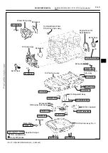
INSTALL OIL PAN SUB
−
ASSY NO.2
(a)
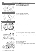
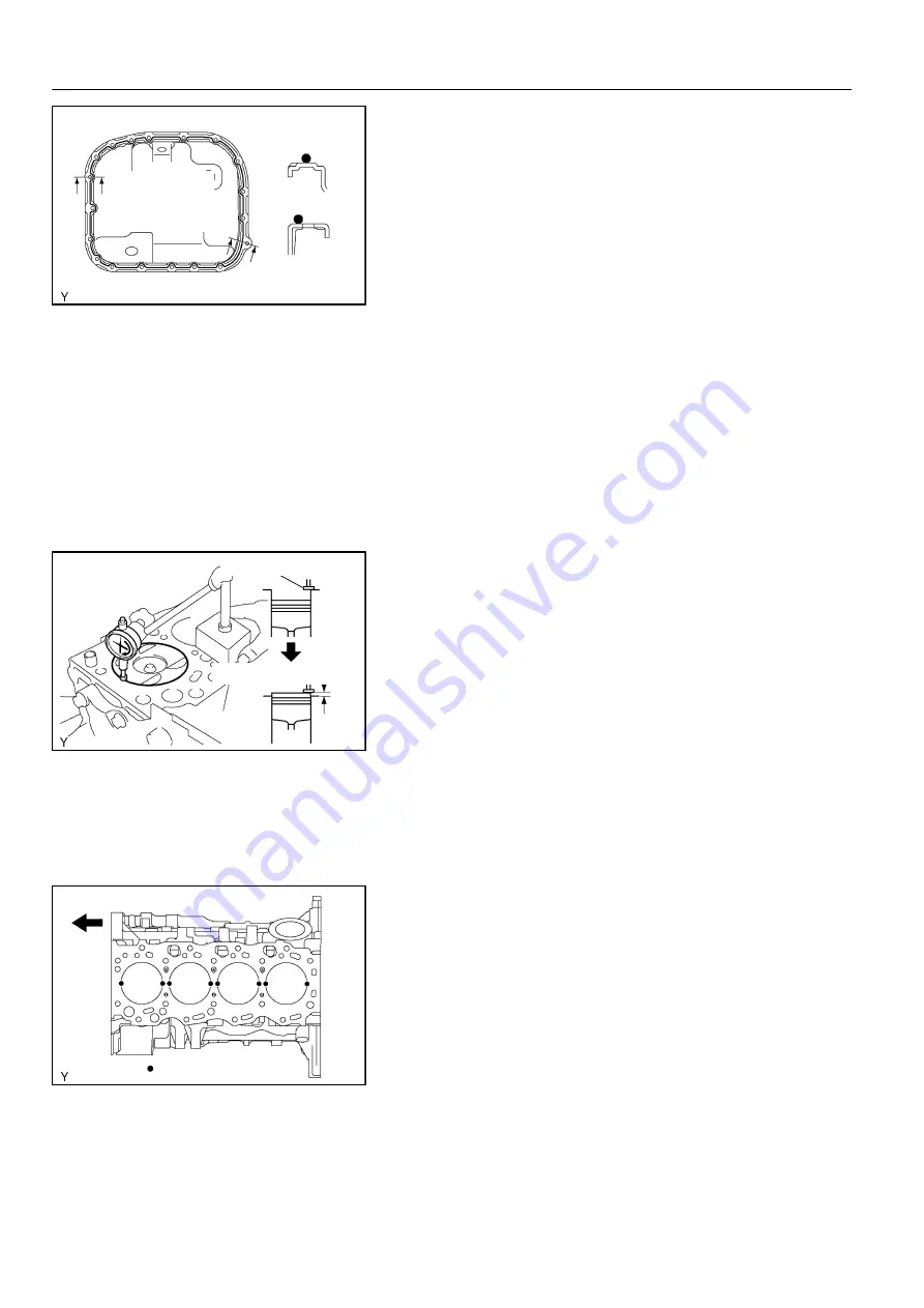
Apply seal packing to the oil pan as shown in the illustra-
tion.
Seal packing: Part No. 08826
−
00080 or equivalent
NOTICE:
S
Install a nozzle of which opening is cut to 4 to 7 mm
(0.16 to 0.28 in.).
S
The parts must be set within 3 minutes and must be
assembled within 15 minutes after applying seal
packing. Otherwise the material must be removed
and reapplied.
S
Immediately remove the nozzle from the tube, then re-
install the cap.
(b)
Install the oil pan with the 16 bolts and 3 nuts. Tighten the
bolts and nuts uniformly in several steps.
Torque: 12 N
×
m (119 kgf
×
cm, 9 ft
×
lbf)
41.
INSTALL CYLINDER HEAD SUB
−
ASSY
(a)
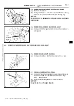
Measure the protrusion height of the piston heads.
(1)
Clean the cylinder block with solvent.
(2)
Set the piston to measure to slightly before the
TDC.
(3)
Place a dial indicator on the cylinder block, then cali-
brate the dial indicator at 0 mm (0 in.).
HINT:
S
Place the measuring tip of the dial indicator as shown in
the illustration.
S
Make sure that the measuring tip is square to the cylinder
block gasket and piston head when measuring.
(4)
Find the most overhung position of the piston head
by slowly turning the crankshaft clockwise and
counterclockwise.
(5)
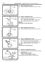
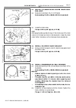
Measure the protrusion height of the piston head for
each cylinder at 2 places as shown in the illustra-
tion. (Total of 8 measurements.)
(6)
Record the higher protrusion height of the 2 mea-
surements at each cylinder.

