A09564
1
18
2
3
4
5
6
7
8
9
(A)
10
11
12
13
14
15
16
17
(B)
(A)
(A)
(A)
(A)
(A)
(A)
(A)
(B)
(B)
(B)
(B)
(B)
(B)
(B)
(B)
(B)
90
_
90
_
90
_
90
_
90
_
90
_
A09565
Painted
Mark
A09624
14
−
16
−
ENGINE MECHANICAL
PARTIAL ENGINE ASSY (1CD
−
FTV)(From September,
2003)
1CD
−
FTV ENGINE REPAIR MANUAL (RM1046E)
(e)
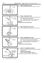
Install the cylinder head bolts.
HINT:
S
The cylinder head bolts are tightened in 4 successive
steps (steps (3), (5), (6) and (7)).
S
If the cylinder head bolt is broken or deformed, replace it
with a new bolt.
(1)
Apply a light coat of engine oil to the threads of the
cylinder head bolts and plate washers.
(2)
Install the plate washer to the cylinder head bolt.
(3)
Using several steps, install and tighten the 18 cylin-
der head bolts uniformly in the sequence shown in
the illustration.
Torque: 45 N
×
m (459 kgf
×
cm, 33 ft
×
lbf)
HINT:
See the table below for the bolt length.
Bolt Type
Bolt Length
(A)
160 mm (6.30 in.)
(B)
104 mm (4.09 in.)
If the cylinder head bolt does not meet the specified torque, re-
place the cylinder head bolt with a new bolt.
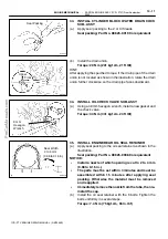
(4)
Mark the front of the cylinder head bolt with paint.
(5)
Retighten the cylinder head bolts by 90
_
in the
same sequence as step (3).
(6)
Retighten the cylinder head bolts by an additional
90
_
in the same sequence as step (3).
(7)
Retighten the cylinder head bolts by one more addi-
tional 90
_
in the same sequence as step (3).
(8)
Check that each painted mark is now at the intake
manifold side.
42.
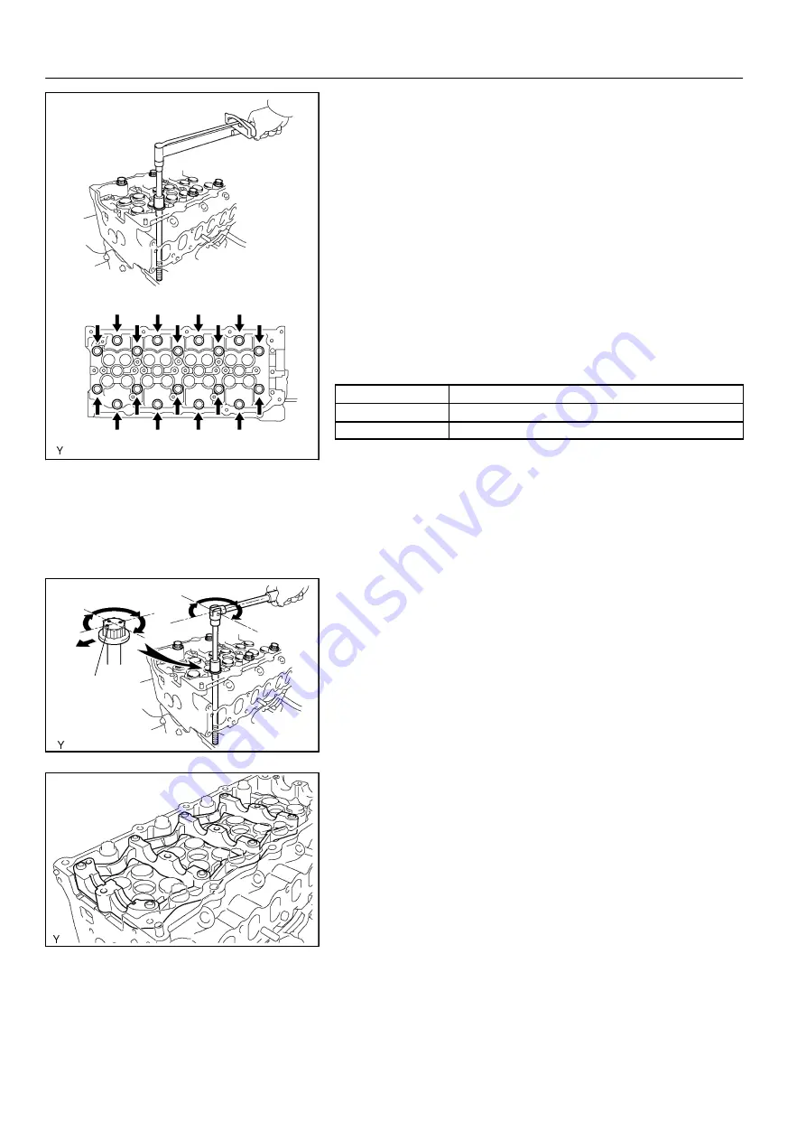
INSTALL CAMSHAFT
(a)
Place the camshaft carrier on the cylinder head.

