EM-91
ENGINE MECHANICAL - Cylinder Block
(j) Remove the main bearing cap bolts and cap.
(k) Measure the Plastigage at its widest point.
Standard clearance:
STD 0.036-0.054 mm
(0.0014-0.0021 in.)
U/S 0.25 and U/S 0.50 0.037-0.077 mm
(0.0015-0.0030 in.)
Maximum clearance: 0.10 mm (0.0039 in.)
If the oil clearance is greater than maximum, replace the
bearings. If necessary, grind or replace the crankshaft.
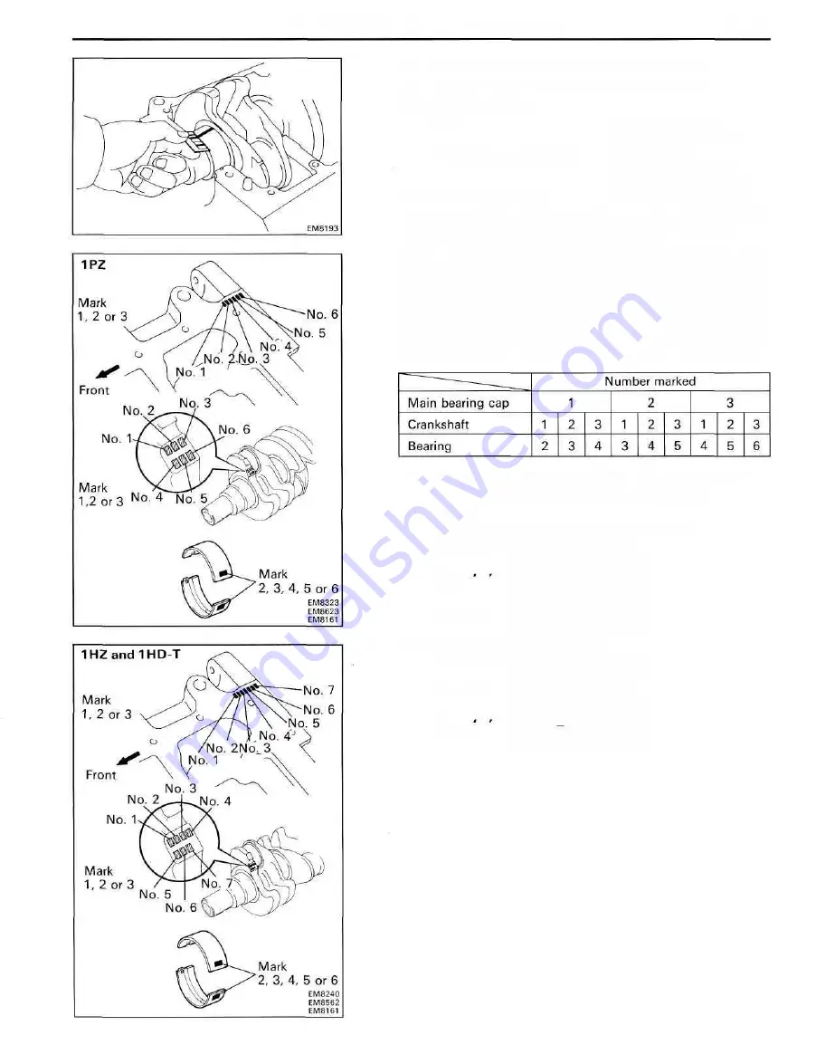
HINT: If using a standard bearing, replace with one
having the same number. If the number of the bearing
cannot be determined, select the correct bearing by adding
together the numbers inprinted on the main bearing cap
and crankshaft, then selecting the bearing with the same
number as the total. There are five sizes of standard
bearings, marked " 2 " , "3", "4", " 5 " and " 6 " accordingly.
EXAMPLE: Main bearing cap " 2 " " + Crankshaft " 1 "
= Total number (Use bearing "3")
(Reference)
Cylinder block main journal bore diameter:
Mark " 1 " 71.000 - 71.006 mm
(2.7953-2.7955 in.)
Mark "2 " 71.006 - 71.012 mm
(2.7955-2.7957 in.)
Mark "3" 71.012-71.018 mm
(2.7957-2.7960 in.)
Crankshaft journal diameter:
Mark " 1 " 66.994-67.000 mm
(2.6376-2.6378 in.)
Mark "2" 66.988-66.994 mm
(2.6373-2.6376 in.)
Mark "3" 66.982 66.988 mm
(2.6371-2.6373 in.)
Summary of Contents for 1HD-T
Page 1: ......
Page 53: ...EM 42 ENGINE MECHANICAL Timing Gears TIMING GEARS COMPONENTS ...
Page 65: ...EM 54 ENGINE MECHANICAL Cylinder Head CYLINDER HEAD COMPONENTS ...
Page 95: ...EM 84 ENGINE MECHANICAL Cylinder Block CYLINDER BLOCK COMPONENTS ...
Page 133: ...TURBOCHARGER SYSTEM Turbocharger TC 9 COMPONENTS ...
Page 145: ...FU 6 FUEL SYSTEM Fuel Heater System FUEL HEATER SYSTEM SYSTEM CIRCUIT ...
Page 166: ...FUEL SYSTEM Injection Pump FU 27 INJECTION PUMP REMOVAL OF INJECTION PUMP ...
Page 169: ...FU 30 FUEL SYSTEM Injection Pump COMPONENTS ...
Page 170: ...FUEL SYSTEM Injection Pump FU 31 COMPONENTS Cont d ...
Page 171: ...FU 32 FUEL SYSTEM Injection Pump COMPONENTS Cont d ...
Page 251: ...LU 4 LUBRICATION SYSTEM Troubleshooting TROUBLESHOOTING ...
Page 255: ...LU 8 LUBRICATION SYSTEM Oil Pump OIL PUMP COMPONENT ...
Page 272: ...ST 4 STARTING SYSTEM Pre Heating System Super Glow Type TIMER CHARACTERISTIC DIAGRAM Cont d ...
Page 282: ...ST 14 STARTING SYSTEM Starting System Circuit STARTING SYSTEM CIRCUIT Cont d ...
Page 340: ...B 1 STANDARD BOLT TORQUE SPECIFICATIONS Page STANDARD BOLT TORQUE SPECIFICATIONS B 2 ...
Page 343: ...C 1 SSTAND SSM Page SST SPECIAL SERVICE TOOLS C 2 SSM SPECIAL SERVICE MATERIALS C 6 ...


