EM-98
ENGINE MECHANICAL - Cylinder Block
(b) Measure the cylinder bore diameter in the thrust
directions. (See step 5 on page EM-93)
(c) Subtract the piston diameter measurement from the
cylinder bore diameter measurement.
Standard oil clearance: 0.04-0.06 mm
(0.0016-0.0024 in.)
Maximum oil clearance: 0.14 mm (0.0055 in.)
If the oil clearance is greater than maximum, replace all five
(1 PZ) or six (1 HZ and 1 HD-T) pistons and rebore all five
(1 PZ) or six (1 HZ and 1HD-T) cylinders. If necessary,
replace the cylinder block.
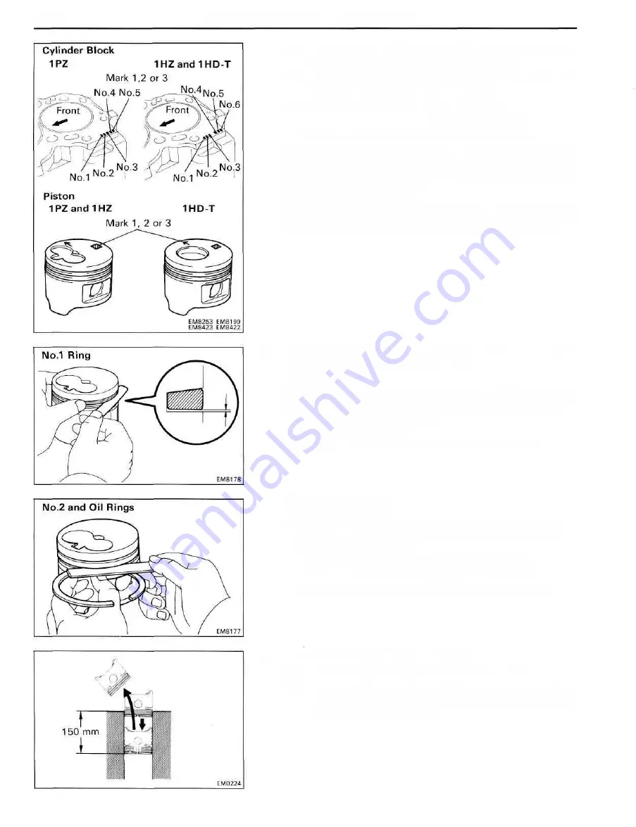
HINT (Use cylinder block subassembly): When installing
a standard piston, install one with the same number mark as
the standard bore diameter mark on the cylinder block.
3. INSPECT CLEARANCE BETWEEN WALL OF RING
GROOVE AND NEW PISTON RING
(No.1 Ring)
Install new No.1 piston ring to the piston. Using a thickness
gauge, measure the clearance between the piston ring and
wall of the piston ring groove.
Ring groove clearance:
No.1 0.050-0.095 mm (0.0020-0.0037 in.)
(No.2 and Oil Rings)
Using a thickness gauge, measure the clearance between
new piston ring and the wall of the piston ring groove.
Ring groove clearance:
No.2 0.06-0.10 mm (0.0024-0.0039 in.)
Oil 0.03-0.07 mm (0.0012-0.0028 in.)
If the clearance is not as specified, replace the piston.
4. INSPECT PISTON RING END CAP
(a) Insert the piston ring into the cylinderbore.
(b) Using a piston, push the piston ring a little beyond the
bottom of the ring travel, 1 50 mm (5.91 in.) from the
top of the cylinder block.
Summary of Contents for 1HD-T
Page 1: ......
Page 53: ...EM 42 ENGINE MECHANICAL Timing Gears TIMING GEARS COMPONENTS ...
Page 65: ...EM 54 ENGINE MECHANICAL Cylinder Head CYLINDER HEAD COMPONENTS ...
Page 95: ...EM 84 ENGINE MECHANICAL Cylinder Block CYLINDER BLOCK COMPONENTS ...
Page 133: ...TURBOCHARGER SYSTEM Turbocharger TC 9 COMPONENTS ...
Page 145: ...FU 6 FUEL SYSTEM Fuel Heater System FUEL HEATER SYSTEM SYSTEM CIRCUIT ...
Page 166: ...FUEL SYSTEM Injection Pump FU 27 INJECTION PUMP REMOVAL OF INJECTION PUMP ...
Page 169: ...FU 30 FUEL SYSTEM Injection Pump COMPONENTS ...
Page 170: ...FUEL SYSTEM Injection Pump FU 31 COMPONENTS Cont d ...
Page 171: ...FU 32 FUEL SYSTEM Injection Pump COMPONENTS Cont d ...
Page 251: ...LU 4 LUBRICATION SYSTEM Troubleshooting TROUBLESHOOTING ...
Page 255: ...LU 8 LUBRICATION SYSTEM Oil Pump OIL PUMP COMPONENT ...
Page 272: ...ST 4 STARTING SYSTEM Pre Heating System Super Glow Type TIMER CHARACTERISTIC DIAGRAM Cont d ...
Page 282: ...ST 14 STARTING SYSTEM Starting System Circuit STARTING SYSTEM CIRCUIT Cont d ...
Page 340: ...B 1 STANDARD BOLT TORQUE SPECIFICATIONS Page STANDARD BOLT TORQUE SPECIFICATIONS B 2 ...
Page 343: ...C 1 SSTAND SSM Page SST SPECIAL SERVICE TOOLS C 2 SSM SPECIAL SERVICE MATERIALS C 6 ...


