FUEL SYSTEM - Injection Nozzles (1 PZ and 1 HZ)
FU-11
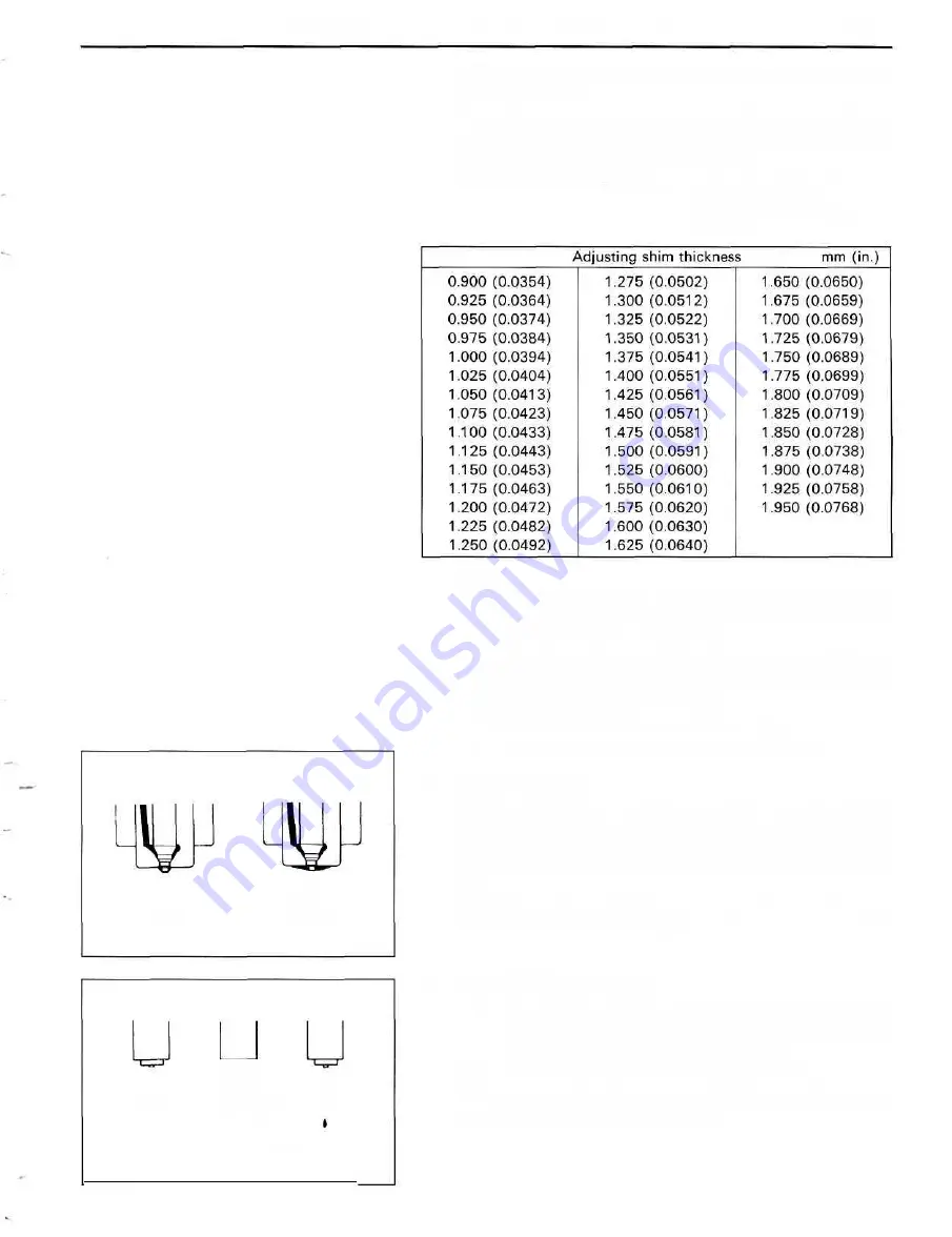
HINT: Proper nozzle operation can be determined by a
swishing sound.
If the opening pressure is not as specified, disassemble he
nozzle holder and change the adjusting shim on the top of
the pressure spring. (See page FU-13).
Adjusted opening pressure: 135- 155 kg/cm
2
(1,920-2.205 psi)
(13,239-15,200 kPa)
Good Faulty
FU1347
Good Faulty
FU1481
HINT:
• Varying the adjusting shim thickness by 0.025 mm
(0.0010 in.) changes the injection pressure by about 4.5
kg/cm
2
(64 psi, 441 kPa) (1PZ).
• Varying the adjusting shim thickness by 0.025 mm
(0.0010 in.) changes the injection pressure by about 3.5
kg/cm
2
(50 psi, 343 kPa) (1HZ).
• Only one adjusting shim should be used.
(f) There should be no dripping after injection.
2. LEAKAGE TEST
While maintaining pressure at about 1 0 - 2 0 kg/cm
2
(142-284 psi, 981 -1,961 kPa) below opening pressure
(adjust by tester handle), check that there is no dripping for
10 seconds from the injection hole or around the retaining
nut.
If the nozzle drips within 10 seconds, replace or clean and
overhaul the nozzle assembly.
3. SPRAY PATTERN TEST
(a) The injection nozzle should shudder at a certain
pumping speed between 15 - 60 times (old nozzle) or
30 - 60 times (new nozzle) per minute.
(b) Check the spray pattern during shuddering.
If the spray pattern is not correct during shuddering, the
nozzle must be replaced or cleaned.
Summary of Contents for 1HD-T
Page 1: ......
Page 53: ...EM 42 ENGINE MECHANICAL Timing Gears TIMING GEARS COMPONENTS ...
Page 65: ...EM 54 ENGINE MECHANICAL Cylinder Head CYLINDER HEAD COMPONENTS ...
Page 95: ...EM 84 ENGINE MECHANICAL Cylinder Block CYLINDER BLOCK COMPONENTS ...
Page 133: ...TURBOCHARGER SYSTEM Turbocharger TC 9 COMPONENTS ...
Page 145: ...FU 6 FUEL SYSTEM Fuel Heater System FUEL HEATER SYSTEM SYSTEM CIRCUIT ...
Page 166: ...FUEL SYSTEM Injection Pump FU 27 INJECTION PUMP REMOVAL OF INJECTION PUMP ...
Page 169: ...FU 30 FUEL SYSTEM Injection Pump COMPONENTS ...
Page 170: ...FUEL SYSTEM Injection Pump FU 31 COMPONENTS Cont d ...
Page 171: ...FU 32 FUEL SYSTEM Injection Pump COMPONENTS Cont d ...
Page 251: ...LU 4 LUBRICATION SYSTEM Troubleshooting TROUBLESHOOTING ...
Page 255: ...LU 8 LUBRICATION SYSTEM Oil Pump OIL PUMP COMPONENT ...
Page 272: ...ST 4 STARTING SYSTEM Pre Heating System Super Glow Type TIMER CHARACTERISTIC DIAGRAM Cont d ...
Page 282: ...ST 14 STARTING SYSTEM Starting System Circuit STARTING SYSTEM CIRCUIT Cont d ...
Page 340: ...B 1 STANDARD BOLT TORQUE SPECIFICATIONS Page STANDARD BOLT TORQUE SPECIFICATIONS B 2 ...
Page 343: ...C 1 SSTAND SSM Page SST SPECIAL SERVICE TOOLS C 2 SSM SPECIAL SERVICE MATERIALS C 6 ...


