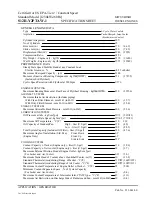
FUEL SYSTEM - Injection Pump FU-87
(i) Using a 5 mm hexagon wrench, adjust by turning the
governor shaft, and perform the measurement again it
is as specified.
HINT: The injection volume will increase approx. 3 cc
(0.2 cu in.) with each 1 /2 turn of the governor shaft.
(j) (1PZand1HZ)
Check the end point injection volume by slowly
moving the adjusting lever from the maximum speed
side to the idle speed side, and secure it at the point
where the pump inner pressure stops dropping.
(k) (1HD-T (Europe))
Check the timer piston stroke when the the pump rpm
is 1,440 rpm and injection volume is 8.4-9.2 cc
(0.51 - 0 . 5 6 cu in.).
Timer piston stroke: 2.0 mm (0.079 in.) or less
(I) (1HD-T (Others))
Check the injection volume when the pump rpm is
1,440 rpm and timer piston stroke is 3.7-4.3 mm
(0.146- 0.169 in.).
Injection volume: 6 cc (0.37 cu in.)
HINT: The end point for 1HD-T engine is hard to iden-
tify, so use the methods used in (k) or (I) above.
(m) Check the timer piston fluctuation when the adjusting
lever is moved from the maximum speed side to the
idle speed side.
Summary of Contents for 1HD-T
Page 1: ......
Page 53: ...EM 42 ENGINE MECHANICAL Timing Gears TIMING GEARS COMPONENTS ...
Page 65: ...EM 54 ENGINE MECHANICAL Cylinder Head CYLINDER HEAD COMPONENTS ...
Page 95: ...EM 84 ENGINE MECHANICAL Cylinder Block CYLINDER BLOCK COMPONENTS ...
Page 133: ...TURBOCHARGER SYSTEM Turbocharger TC 9 COMPONENTS ...
Page 145: ...FU 6 FUEL SYSTEM Fuel Heater System FUEL HEATER SYSTEM SYSTEM CIRCUIT ...
Page 166: ...FUEL SYSTEM Injection Pump FU 27 INJECTION PUMP REMOVAL OF INJECTION PUMP ...
Page 169: ...FU 30 FUEL SYSTEM Injection Pump COMPONENTS ...
Page 170: ...FUEL SYSTEM Injection Pump FU 31 COMPONENTS Cont d ...
Page 171: ...FU 32 FUEL SYSTEM Injection Pump COMPONENTS Cont d ...
Page 251: ...LU 4 LUBRICATION SYSTEM Troubleshooting TROUBLESHOOTING ...
Page 255: ...LU 8 LUBRICATION SYSTEM Oil Pump OIL PUMP COMPONENT ...
Page 272: ...ST 4 STARTING SYSTEM Pre Heating System Super Glow Type TIMER CHARACTERISTIC DIAGRAM Cont d ...
Page 282: ...ST 14 STARTING SYSTEM Starting System Circuit STARTING SYSTEM CIRCUIT Cont d ...
Page 340: ...B 1 STANDARD BOLT TORQUE SPECIFICATIONS Page STANDARD BOLT TORQUE SPECIFICATIONS B 2 ...
Page 343: ...C 1 SSTAND SSM Page SST SPECIAL SERVICE TOOLS C 2 SSM SPECIAL SERVICE MATERIALS C 6 ...


