EM-75
ENGINE MECHANICAL Cylinder Head
INSTALLATION OF CYLINDER HEAD
(See page EM-54)
1. CHECK PISTON PROTRUSION AND SELECT
CYLINDER HEAD GASKET
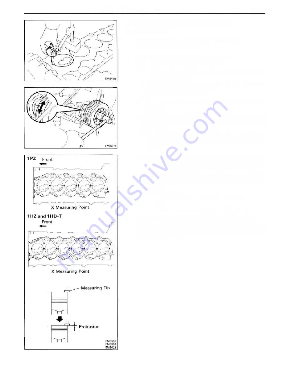
A. Check piston protrusions each cylinder
(a) Clean the cylinder block solvent.
(b) Set the piston of the cylinder to be measured to
slightly befor TDC.
(c) Place a dial indicator on the cylinder block, and set the
dial indicator at 0 mm (0 in.)
HINT:
• Use a dial indicator measuring tip as shown in the
illustration.
• Make sure that the measuring tip is sqaure to the cylinder
block gasket surface and piston head when taking the
measurments.
(d) Find where the piston head protrudes most by slowly
turning the crankshaft clockwise and counterclock-
wise.
(e) Measure each cylinder at two places as shown in
the illustration, making a tatal of ten measurements
(1PZ) or twelve measurements (1 HZ and 1HD-T).
(f) For the piston protrusion value of each cylinder, use
the average of the two measurements of each cylinder.
Protrusion:
IPZ and 1HZ
0.405-0.655 mm (0.0159-0.0258 in.)
1HD-T
0.475-0.725 mm (0.0187-0.0285 in.)
(When removing piston and connecting rod assembly)
If the protrusion is not as specified, remove the piston and
connecting rod assembly (See page EM-86) and reinstall it
(See page EM-108).
Summary of Contents for 1HD-T
Page 1: ......
Page 53: ...EM 42 ENGINE MECHANICAL Timing Gears TIMING GEARS COMPONENTS ...
Page 65: ...EM 54 ENGINE MECHANICAL Cylinder Head CYLINDER HEAD COMPONENTS ...
Page 95: ...EM 84 ENGINE MECHANICAL Cylinder Block CYLINDER BLOCK COMPONENTS ...
Page 133: ...TURBOCHARGER SYSTEM Turbocharger TC 9 COMPONENTS ...
Page 145: ...FU 6 FUEL SYSTEM Fuel Heater System FUEL HEATER SYSTEM SYSTEM CIRCUIT ...
Page 166: ...FUEL SYSTEM Injection Pump FU 27 INJECTION PUMP REMOVAL OF INJECTION PUMP ...
Page 169: ...FU 30 FUEL SYSTEM Injection Pump COMPONENTS ...
Page 170: ...FUEL SYSTEM Injection Pump FU 31 COMPONENTS Cont d ...
Page 171: ...FU 32 FUEL SYSTEM Injection Pump COMPONENTS Cont d ...
Page 251: ...LU 4 LUBRICATION SYSTEM Troubleshooting TROUBLESHOOTING ...
Page 255: ...LU 8 LUBRICATION SYSTEM Oil Pump OIL PUMP COMPONENT ...
Page 272: ...ST 4 STARTING SYSTEM Pre Heating System Super Glow Type TIMER CHARACTERISTIC DIAGRAM Cont d ...
Page 282: ...ST 14 STARTING SYSTEM Starting System Circuit STARTING SYSTEM CIRCUIT Cont d ...
Page 340: ...B 1 STANDARD BOLT TORQUE SPECIFICATIONS Page STANDARD BOLT TORQUE SPECIFICATIONS B 2 ...
Page 343: ...C 1 SSTAND SSM Page SST SPECIAL SERVICE TOOLS C 2 SSM SPECIAL SERVICE MATERIALS C 6 ...


