IN-5
INTRODUCTION - General Repair Instructions
(b) Recoating of Precoated Parts
(1) Clean off the old adhesive from the part's
threads.
(2) Dry with compressed air.
(3) Apply the specified seal lock adhesive to the
part's threads.
(c) Precoated parts are indicated in the component illus-
trations by the " * " symbol.
7. When necessary, use a sealer on gaskets to prevent leaks.
8. Carefully observe all specifications for bolt torques. Always
use a torque wrench.
9. Use of special service tools (SST) and special service
materials (SSM) may be required, depending on the nature
of the repair. Be sure to use SST and SSM where specified
and follow the proper work procedure. A list of SST and
SSM can be found at the back of this manual.
10. When replacing fuses, be sure the new fuse is the correct
amperage. DO NOT exceed the rating or use one of a lower
rating.
11. Care must be taken when jacking up and supporting the
vehicle. Be sure to lift and support the vehicle at the proper
locations.
(a) If the vehicle is to be jacked up only at the front or rear
end, be sure to block the wheels in order to ensure
safety.
(b) After the vehicle is jacked up, be sure to support it on
stands. It is extremely dangerous to do any work on
the vehicle raised on a jack alone, even for a small job
that can be finished quickly.
12. Observe the following precautions to avoid damaging the
parts:
(a) Be careful not to drop electrical components, such as
sensors or relays. If they are dropped on a hard floor,
they should be replaced and not reused.
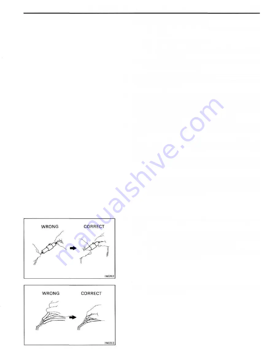
(b) To pull apart electrical connectors, pull on the con-
nector itself, not the wires.
(c) To disconnect vacuum hoses, pull on the end, not the
middle of the hose.
Summary of Contents for 1HD-T
Page 1: ......
Page 53: ...EM 42 ENGINE MECHANICAL Timing Gears TIMING GEARS COMPONENTS ...
Page 65: ...EM 54 ENGINE MECHANICAL Cylinder Head CYLINDER HEAD COMPONENTS ...
Page 95: ...EM 84 ENGINE MECHANICAL Cylinder Block CYLINDER BLOCK COMPONENTS ...
Page 133: ...TURBOCHARGER SYSTEM Turbocharger TC 9 COMPONENTS ...
Page 145: ...FU 6 FUEL SYSTEM Fuel Heater System FUEL HEATER SYSTEM SYSTEM CIRCUIT ...
Page 166: ...FUEL SYSTEM Injection Pump FU 27 INJECTION PUMP REMOVAL OF INJECTION PUMP ...
Page 169: ...FU 30 FUEL SYSTEM Injection Pump COMPONENTS ...
Page 170: ...FUEL SYSTEM Injection Pump FU 31 COMPONENTS Cont d ...
Page 171: ...FU 32 FUEL SYSTEM Injection Pump COMPONENTS Cont d ...
Page 251: ...LU 4 LUBRICATION SYSTEM Troubleshooting TROUBLESHOOTING ...
Page 255: ...LU 8 LUBRICATION SYSTEM Oil Pump OIL PUMP COMPONENT ...
Page 272: ...ST 4 STARTING SYSTEM Pre Heating System Super Glow Type TIMER CHARACTERISTIC DIAGRAM Cont d ...
Page 282: ...ST 14 STARTING SYSTEM Starting System Circuit STARTING SYSTEM CIRCUIT Cont d ...
Page 340: ...B 1 STANDARD BOLT TORQUE SPECIFICATIONS Page STANDARD BOLT TORQUE SPECIFICATIONS B 2 ...
Page 343: ...C 1 SSTAND SSM Page SST SPECIAL SERVICE TOOLS C 2 SSM SPECIAL SERVICE MATERIALS C 6 ...


