EM-79
ENGINE MECHANICAL - Cylinder Head
(f) (1HZ and 1HD-T)
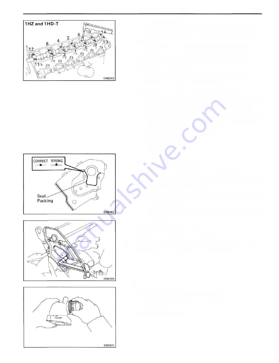
Install and uniformly tighten the fourteen bearing
cap bolts in several passes in the sequence shown.
Torque:
No.1 journal 250 kg-cm (18 ft-lb, 25 N-m)
Others 185 kg-cm (13 ft-lb, 18 N-m)
5. ADJUST VALVE CLEARANCE (See page EM-19)
Valve clearance (Cold):
Intake 0.15-0.25 mm (0.006-0.010 in.)
Exhaust 0.35-0.45 mm (0.014-0.018 in.)
6. INSTALL CAMSHAFT OIL SEAL RETAINER
(a) Remove any old packing (FIPG) material and be
careful not to drop any oil on the contact surfaces of
the camshaft oil seal retainer and cylinder head.
• Using a razor blade and gasket scraper, remove all
the old packing (FIPG) material from the gasket
surfaces and sealing groove.
• Thoroughly clean all components to remove all the
loose material.
• Using a non-residue solvent, clean both sealing
surfaces.
(b) Apply seal packing to the camshaft oil seal retainer as
shown in the illustration.
Seal packing: Part No.08826-00080 or equivalent
• Install a nozzle that has been cut to a 2 - 3 mm
(0.08-0.12 in.) opening.
• Parts must be assembled within 5 minutes of appli-
cation. Otherwise the material must be removed
and reapplied.
• Immediately remove nozzle from the tube and rein-
stall cap.
(c) Install the retainer with the four bolts.
Torque: 200 kg-cm (14 ft-lb, 20 N-m)
7. INSTALL PULLEYS AND TIMING BELT
(See steps 2 to 4 and 6 to 11 on pages EM-38 to 41)
8. (1HZand1HD-T)
ASSEMBLY EXHAUST MANIFOLDS
(a) Remove all the O-ring material from the manifold
grooves.
(b) Install new O-rings.
Summary of Contents for 1HD-T
Page 1: ......
Page 53: ...EM 42 ENGINE MECHANICAL Timing Gears TIMING GEARS COMPONENTS ...
Page 65: ...EM 54 ENGINE MECHANICAL Cylinder Head CYLINDER HEAD COMPONENTS ...
Page 95: ...EM 84 ENGINE MECHANICAL Cylinder Block CYLINDER BLOCK COMPONENTS ...
Page 133: ...TURBOCHARGER SYSTEM Turbocharger TC 9 COMPONENTS ...
Page 145: ...FU 6 FUEL SYSTEM Fuel Heater System FUEL HEATER SYSTEM SYSTEM CIRCUIT ...
Page 166: ...FUEL SYSTEM Injection Pump FU 27 INJECTION PUMP REMOVAL OF INJECTION PUMP ...
Page 169: ...FU 30 FUEL SYSTEM Injection Pump COMPONENTS ...
Page 170: ...FUEL SYSTEM Injection Pump FU 31 COMPONENTS Cont d ...
Page 171: ...FU 32 FUEL SYSTEM Injection Pump COMPONENTS Cont d ...
Page 251: ...LU 4 LUBRICATION SYSTEM Troubleshooting TROUBLESHOOTING ...
Page 255: ...LU 8 LUBRICATION SYSTEM Oil Pump OIL PUMP COMPONENT ...
Page 272: ...ST 4 STARTING SYSTEM Pre Heating System Super Glow Type TIMER CHARACTERISTIC DIAGRAM Cont d ...
Page 282: ...ST 14 STARTING SYSTEM Starting System Circuit STARTING SYSTEM CIRCUIT Cont d ...
Page 340: ...B 1 STANDARD BOLT TORQUE SPECIFICATIONS Page STANDARD BOLT TORQUE SPECIFICATIONS B 2 ...
Page 343: ...C 1 SSTAND SSM Page SST SPECIAL SERVICE TOOLS C 2 SSM SPECIAL SERVICE MATERIALS C 6 ...


