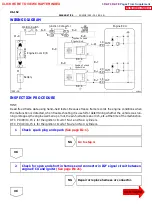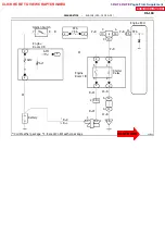
A02284
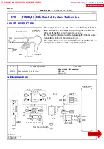
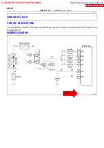
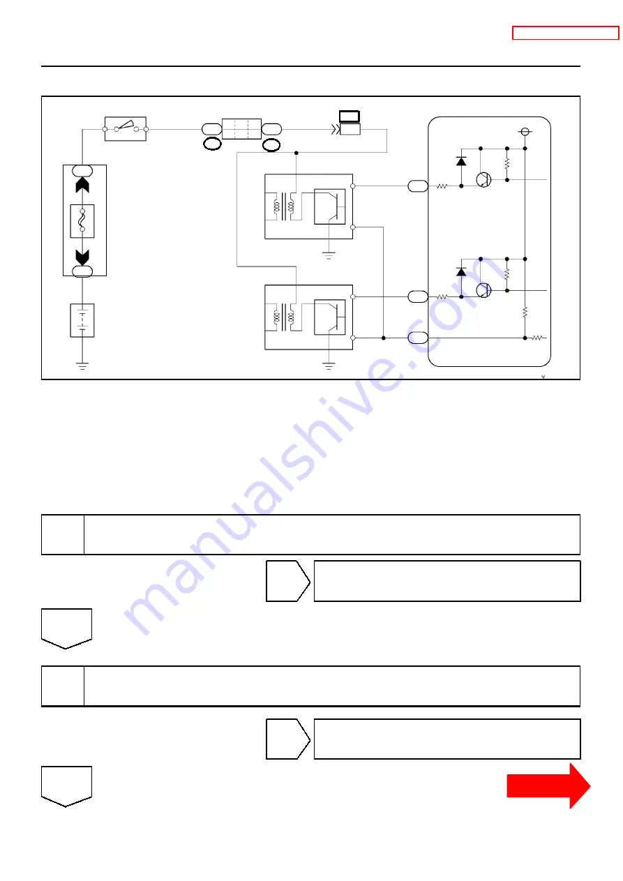
Engine ECU
IGF
IGT2
IGT1
E4
E4
E4
19
16
20
L--W
B--Y
B--Y
2
3
4
1
Ignition Coil and
Igniter No.1
Ignition Coil and
Igniter No.2
B--R
B--R
B--R
B--R
IC3
2
3
4
1
J13
J14
A
C
B--R
6
7
Ignition Switch
2
1
2
2
30A
A
M
2
Battery
W--R
W
B--L
12
BR
BR
IJ4
*
*B J4
*B J3
junction Connector
Engine Room R/B
*2RZ--FE:
DI--152
--
DIAGNOSTICS
ENGINE (2RZ--FE, 3RZ--FE)
WIRING DIAGRAM
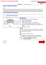
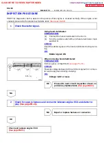
INSPECTION PROCEDURE
HINT:
Read freed frame data using hand--held tester. Because freeze frame records the engine conditions when
the malfunction is detected, when troubleshooting it is useful for determining whether the vehicle was run-
ning or stopped, the engine warmed up or not, the air--fuel ratio lean or rich, etc. at the time of the malfunction.
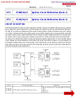
DTC P1300/14,15 is for the ignition circuit of No.1 and No.4 cylinders.
DTC P1310/14,15 is for the ignition circuit of No.2 and No.3 cylinders.
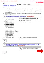
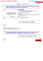
1 Check spark plug and spark
OK
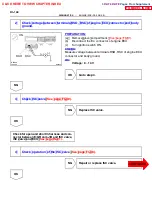
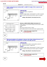
2 Check for open and short in harness and connector in IGF signal circuit between
engine ECU and igniter
NG
Repair or replace harness or connector.
OK
CLICK HERE TO VIEW CHAPTER INDEX
Pages From Supplement
3RZ-F,3RZ-FE

