A02512
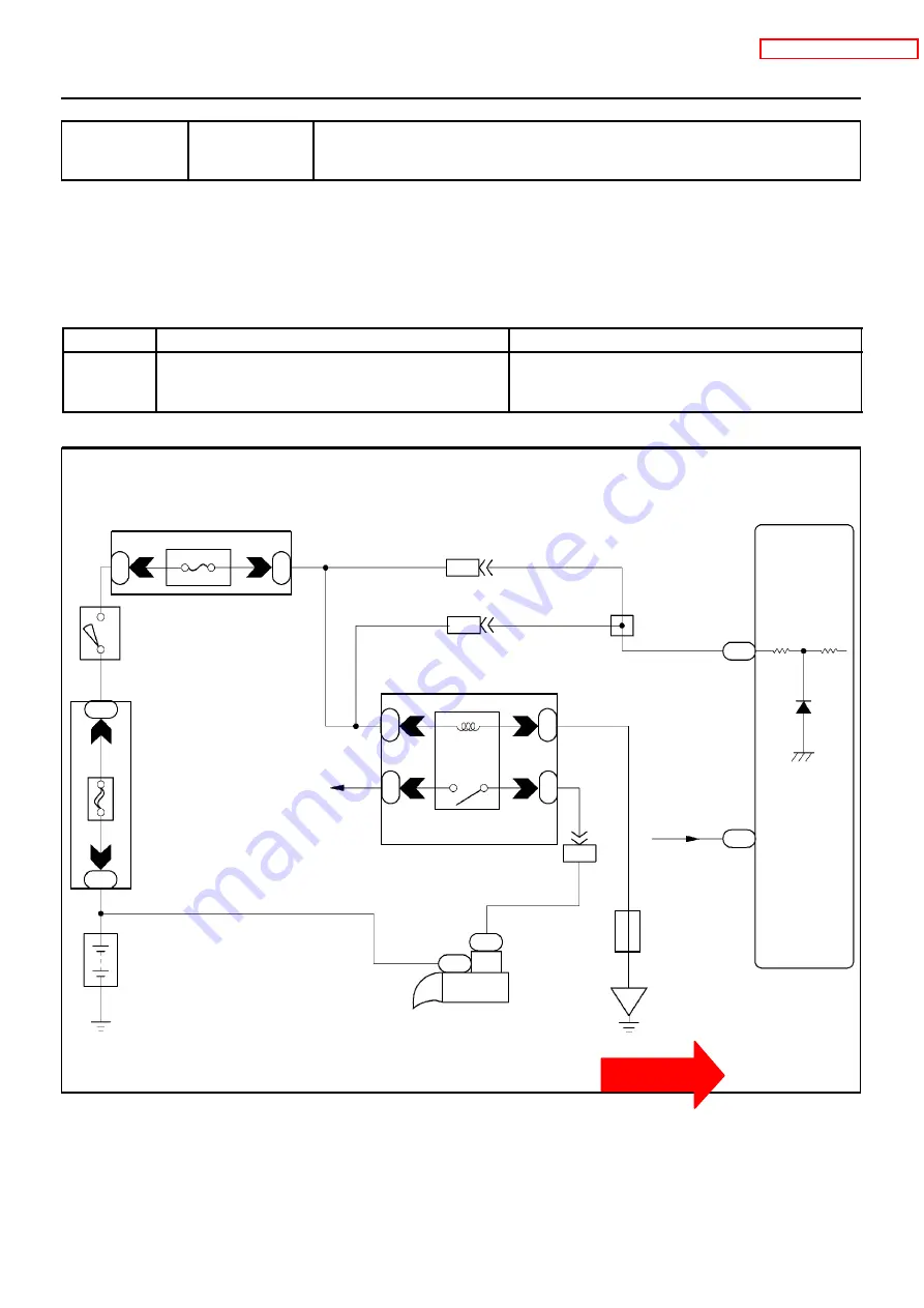
Engine ECU
STA
11
E4
E4 NE--
(NE Signal)
4
P--B
P--B
V--Y
IJ1
15
25
V--Y
P--B
P--B
2
2
2
1
7.5A STA
2
2
1
2
30A
A
M
2
2
2
2
2
1
2
5
3
Starter
Relay
W
B--W
W--B
W--B
EB1
B--W
S2
S3
Starter
B--L
W
Battery
Ignition
Switch
Engine Room J/B
Engine
Room J/B
Engine Room J/B
J12
J/B
IJ1
B
8
7
W--R
1
1
A
A
J/C
W--B
EB
2
DI--42
--
DIAGNOSTICS
ENGINE (1RZ--E)
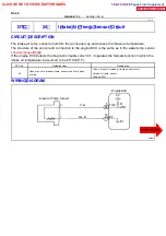
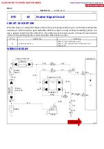
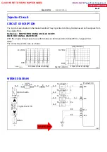
DTC 43 Starter Signal Circuit
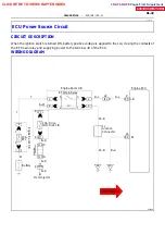
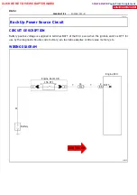
CIRCUIT DESCRIPTION
When the engine is cranked, the intake air flow is slow, so fuel vaporization is poor. A rich mixture is therefore
necessary in order to achieve good startability. While the engine is being cranked, the battery positive volt-
age is applied to terminal STA of the ECU. The starter signal is mainly used to increase the fuel injection
volume for the starting injection control and after--start injection control.
DTC No.
Detection Item
Trouble Area
43
No starter signal to ECU
S
Open or short in starter signal circuit
S
Open or short in ignition switch or starter relay circuit
S
Engine ECU
WIRING DIAGRAM
DI1HV--01
CLICK HERE TO VIEW CHAPTER INDEX
Pages From Supplement
3RZ-F,3RZ-FE


