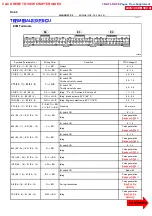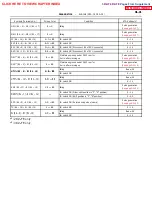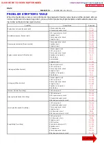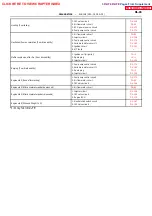
FI4741
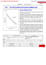
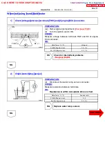
(fig.1)
Acceptable
R
esi
st
an
ce
k
Ω
-- 20
0
20
40
60
80
100
(-- 4)
32
68
104
140
176
212
30
20
10
5
3
2
1
0.5
0.3
0.2
0.1
Temp.
˚
C (F
˚
)
--
DIAGNOSTICS
ENGINE (2RZ--FE, 3RZ--FE)
DI--101
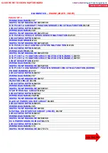
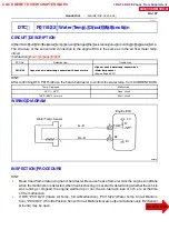
DTC P 0110/ 24 I n take Ai r Tem p. Ci rcui t M al functi on
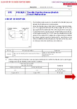
CIRCUIT DESCRIPTION
The intake air temp. sensor is built into the air flow meter and
sensors the intake air temp.
A thermistor built in the sensor changes the resistance value
according to the intake air temp. The lower the intake air temp.
the greater the thermistor resistance value, and the higher the
intake air temp. the lower the thermistor resistance value
(See fig.1).
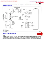
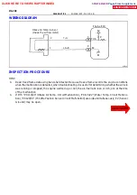
The air intake temp. sensor is connected to the engine ECU
(See below). The 5V power source voltage in the ECU is ap-
plied to the intake air temp. sensor from the terminal THA via
a resistor R.
That is the resistor R and the intake air temp. sensor are con-
nected in series. When the resistance value of the intake air
temp. sensor changes in accordance with changes in the intake
air temp. the potential at terminal THA also changes. Based on
this signal, the engine ECU increases the fuel injection volume
to improve driveability during cold engine operation.
If the engine ECU detects the DTC ”P0110/24”, it operates the
fail safe function in which the intake air temp. is assumed to be
20
˚
C (68
˚
F).
DTC No.
DTC Detecting Condition
Trouble Area
O
h t i i t k
i t
i
it f 0 5
S
Open or short in intake air temp. sensor circuit
P0110/24
Open or short in intake air temp. sensor circuit for 0.5 sec or
more
S
Open or short in intake air temp. sensor circuit
S
Intake air temp. sensor
P0110/24
more
Intake air temp. sensor
S
Engine ECU
HINT:
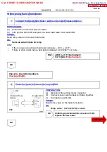
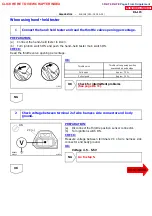
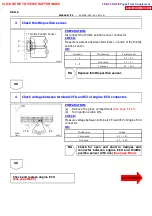
After confirming DTC P110/24 use the hand--held tester to confirm the intake air temp. from ”CURRENT
DATA”.
Temp. Displayed
Malfunction
-- 40
˚
C (-- 40
˚F)
Open circuit
140
˚
C (284
˚F) or more
Short circuit
DI1IC--01
CLICK HERE TO VIEW CHAPTER INDEX
Pages From Supplement
3RZ-F,3RZ-FE

