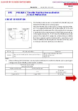
A01858
1
14
E5
OX1
HT1
Engine ECU
HT2
OX2
E1
E5
E5
E5
E4
14
5
6
8
G--B
B
BR
BR
BR
ED
EB
(Bank1 Sensor1)
Oxygen Sensor
Heated
(Bank1 Sensor2)
Oxygen Sensor
Heated
3
2
4
R--L
R--L
R--L
R--L
IJ4
IA2
IA1
22
5
2
2
2
2
3
1
5
2
EFI Relay
Y
1J
1H
8
6
10A
IGN
J3
J3
Ju
nc
tion
C
onnec
tor
From Ignition Switch
B
atte
ry
W
2
2
15A
EFI
2
1
Junc
tion
C
onnec
to
r
W--B
W--B
B--W
1
3
2
4
B--R
B--R
7
R--W
R
(*1)
(*2)
*1 Europe
*2 Except Europe
Engine Room R/B
Drive Side R/B
E
ngine
Room
R/
B
B
B
J1
A
A
DI--120
--
DIAGNOSTICS
ENGINE (2RZ--FE, 3RZ--FE)
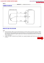
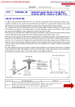
HINT:
S
B
ank 1 refers to the bank that includes cylinder No.1.
S
Sensor 1 is the oxygen sensor of front side.
S
The heated oxygen sensor’s output voltage and the short---term fuel trim value can be read using the
hand---held tester.
S
If voltage output of heated oxygen sensor is 0 V, heated oxygen sensor circuit sensor circuit may be
open or short.
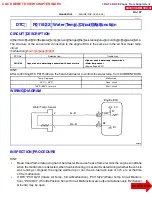
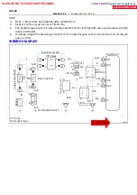
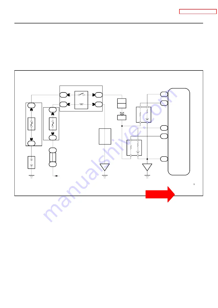
WIRING DIAGRAM
CLICK HERE TO VIEW CHAPTER INDEX
Pages From Supplement
3RZ-F,3RZ-FE

