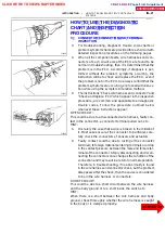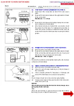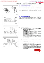
V08423
Knock Sensor
GR
ECU
KNK
E1
12
E6
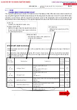
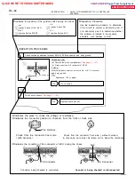
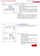
WIRING DIAGRAM
D
Wiring Diagram
This shows a wiring diagram of the circuit.
Use this diagram together with ELECTRICAL
WIRING DIAGRAM to thoroughly understand the
circuit.
Wire colors are indicated by an alphabetical code.
B = Black, L = Blue, R = Red, BR = Brown,
LG = Light Green, V = Violet, G = Green,
O = Orange, W = White, GR = Gray, P = Pink,
Y = Yellow
The first letter indicates the basic wire color and
the second letter indicates the color of the stripe.
DTC
43
Starter Signal Circuit
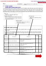
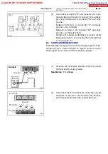
CIRCUIT DESCRIPTION
When the engine is cranked, the intake air flow is slow, so fuel vaporization is poor. A rich mix-
ture is these fore necessary in order to achieve good startability. While the engine is being
cranked, the battery positive voltage is applied to terminal STA of the ECU.
DTC No.
Detection Item
Trouble Area
43
No starter signal to ECU
D
Open or short in signal circuit
D
engine ECU
D
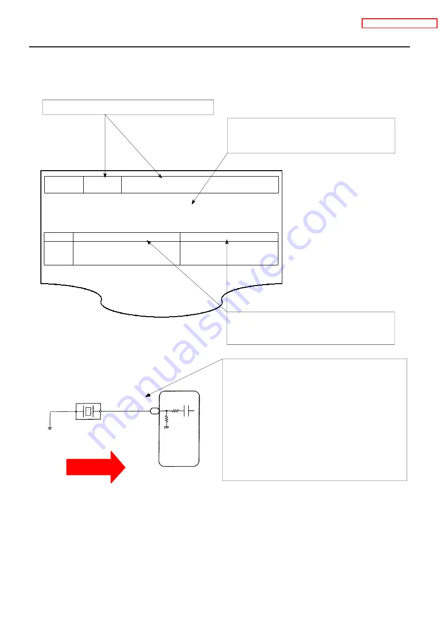
Diagnostic Trouble Code No. and Detection Item
D
Circuit Description
The major role and operation, etc. of the circuit
and its component parts are explained.
D
Indicates the diagnostic trouble code, diagnostic
trouble code set parameter and suspect area of
the problem.
IN--18
--
INTRODUCTION
HOW TO TROUBLESHOOT ECU CONTROLLED
SYSTEMS
7. 1RZ -- FE:
CI RCUI T I NSPECTION
How to read and use each page is shown below.
CLICK HERE TO VIEW CHAPTER INDEX
Pages From Supplement
3RZ-F,3RZ-FE


