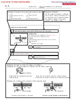
V08423
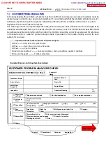
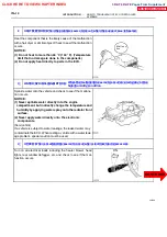
Knock Sensor
GR
ECU
KNK
E1
12
E6
WIRING DIAGRAM
D
Wiring Diagram
This shows a wiring diagram of the circuit.
Use this diagram together with ELECTRICAL
WIRING DIAGRAM to thoroughly understand the
circuit.
Wire colors are indicated by an alphabetical code.
B = Black, L = Blue, R = Red, BR = Brown,
LG = Light Green, V = Violet, G = Green,
O = Orange, W = White, GR = Gray, P = Pink,
Y = Yellow
The first letter indicates the basic wire color and
the second letter indicates the color of the stripe.
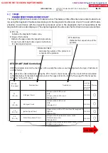
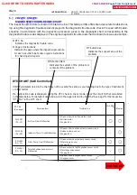
DTC
P0325/52
Knock Sensor Circuit Malfunction
CIRCUIT DESCRIPTION
Knock sensor are fitted to the cylinder block to detect engine knocking. This sensor contains
a piezoelectric element which generates a voltage when it becomes deformed, which occurs
when the cylinder block vibrates due to knocking.
DTC No.
Detection Item
Trouble Area
P0325/52
No knock sensor 1 signal to engine
ECU with engine speed between
1,700 rpm and 5,200 rpm
D
Open or short in knock sensor circuit
D
Knock sensor (Looseness)
D
Engine ECU
D
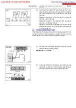
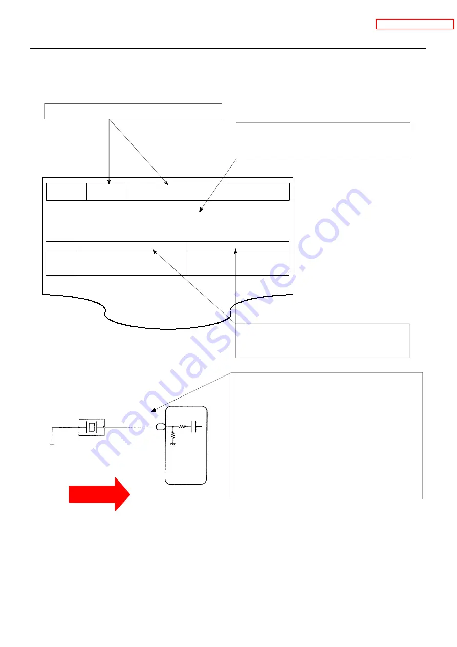
Diagnostic Trouble Code No. and Detection Item
D
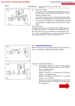
Circuit Description
The major role and operation, etc. of the circuit
and its component parts are explained.
D
Indicates the diagnostic trouble code, diagnostic
trouble code set parameter and suspect area of
the problem.
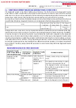
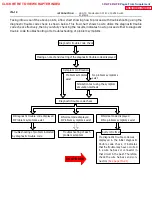
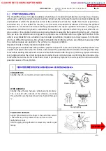
--
INTRODUCTION
HOW TO TROUBLESHOOT ECU CONTROLLED
SYSTEMS
IN--19
8. 2RZ -- FE:, 3RZ -- FE:
CI RCUI T I NSPECTION
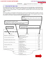
How to read and use each page is shown below.
CLICK HERE TO VIEW CHAPTER INDEX
Pages From Supplement
3RZ-F,3RZ-FE

