P01559
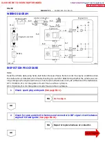
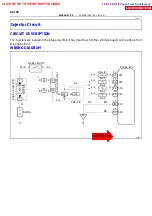
Throttle Valve
To Cylinder
Signal
From
Air
Cleaner
Valve
ISC Valve
Intake Air
Chamber
Engine
ECU
A02255
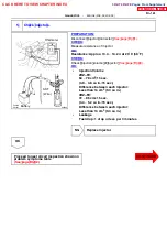
EFI Relay
Junc
tion
Connec
to
r
2
3
1
ISC Valve
Engine ECU
RSC
RSO
E4
E4
B--R
W--L
9
10
R--L
IC3
IJ1
IA1
IA2
2RZ--FE
R--L
R--L
1
22
3
1
5
2
2
2
2
2
A
EB
B--W
B-
-R
IJ
IH
Junction Connector
J14
J14
10A IGN
6
From Ignition Switch
Y
2
2
1
2
Battery
W
W--B
W--B
8
E
F
I15A
Engine Room R/B
*3 2RZ--FE:
*1 Europe
*2 Except Europe
C
C
1J
1H
*3
*3
Drive side J/B
A
J1
R--L
R--L
IJ4
*3 7
(*1)
(*2)
DI--146
--
DIAGNOSTICS
ENGINE (2RZ--FE, 3RZ--FE)
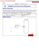
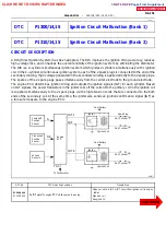
DTC P0505/33 Idle Control System Malfunction
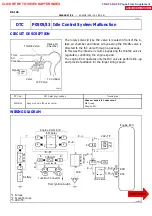
CIRCUIT DESCRIPTION
The rotary solenoid type ISC valve is located in front of the in-
take air chamber and intake air bypassing the throttle valve is
directed to the ISC valve through a passage.
In this way the intake air volume bypassing the throttle valve is
regulated, controlling the engine speed.
The engine ECU operates only the ISC valve to perform idle--up
and provide feedback for the target idling speed.
DTC No.
DTC Detecting Condition
Trouble Area
S
Open or short in ISC valve circuit
P0505/33
Open or short in ISC valve circuit.
S
Open or short in ISC valve circuit
S
ISC valve
P0505/33
Open or short in ISC valve circuit.
ISC valve
S
Engine ECU
WIRING DIAGRAM
DI1IN--01
CLICK HERE TO VIEW CHAPTER INDEX
Pages From Supplement
3RZ-F,3RZ-FE

