P14781
Z10578
4, 5 or 6
P14783
EM--66
--
ENGINE MECHANICAL
CYLINDER BLOCK (2RZ--FE, 3RZ--F)
(j)
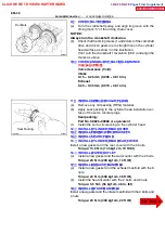
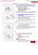
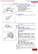
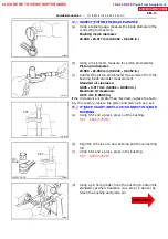
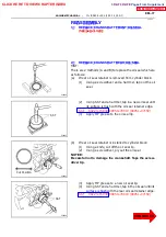
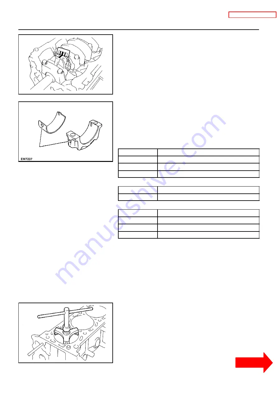
Measure the Plastigage at its widest point.
Standard oil clearance:
STD
0.030 -- 0.055 mm (0.0012 -- 0.0022 in.)
U/S 0.25
0.031 -- 0.071 mm (0.0012 -- 0.0026 in.)
Maximum oil clearance:
0.10 mm (0.0039 in.)
If the oil clearance is greater than maximum, replace the bear-
ings. If necessary, grind or replace the crankshaft.
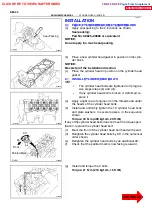
HINT:
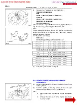
If using a standard bearing, replace with one having the same
number as marked on the bearing cap. There are 3 sizes of
standard bearings, marked
”4”, ”5” and ”6” accordingly.
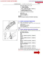
Reference:
Connecting rod big end inside diameter:
STD Mark ”4”
56.000 -- 56.006 mm (2.2047 -- 2.2050 in.)
STD Mark ”5”
56.006 -- 56.012 mm (2.2050 -- 2.2052 in.)
STD Mark ”6”
56.012 -- 56.018 mm (2.2052 -- 2.2054 in.)
U/S 0.25
56.000 -- 56.018 mm (2.2047 -- 2.2054 in.)
Crankshaft crank pin diameter:
STD
52.987 -- 53.000 mm (2.0861 -- 2.0866 in.)
U/S 0.25
52.745 -- 52.755 mm (2.0766 -- 2.0770 in.)
Standard sized bearing center wall thickness:
STD Mark ”4”
1.482 -- 1.485 mm (0.0583 -- 0.0585 in.)
STD Mark ”5”
1.485 -- 1.488 mm (0.0585 -- 0.0586 in.)
STD Mark ”6”
1.488 -- 1.491 mm (0.0586 -- 0.0587 in.)
U/S 0.25
1.601 -- 1.607 mm (0.0630 -- 0.0633 in.)
(k)
Completely remove the Plastigage.
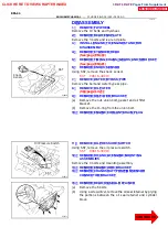
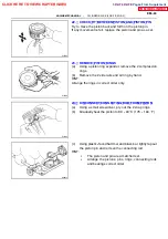
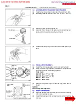
1 8 . RE MO V E P I S TO N AND CO NNE CTI NG RO D
ASSEMBLIES
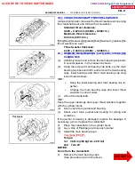
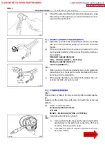
(a)
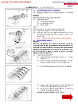
Using a ridge reamer, remove the all carbon from the top
of the cylinder.
(b)
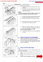
Push the piston, connecting rod assembly and upper
bearing through the top of the cylinder block.
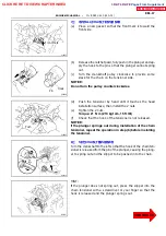
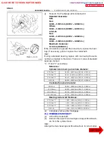
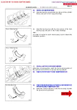
HINT:
S
Keep the bearings, connecting rod and cap togeth-
er.
S
Arrange the piston and connecting rod assemblies
in correct order.
CLICK HERE TO VIEW CHAPTER INDEX
Pages From Supplement
3RZ-F,3RZ-FE

