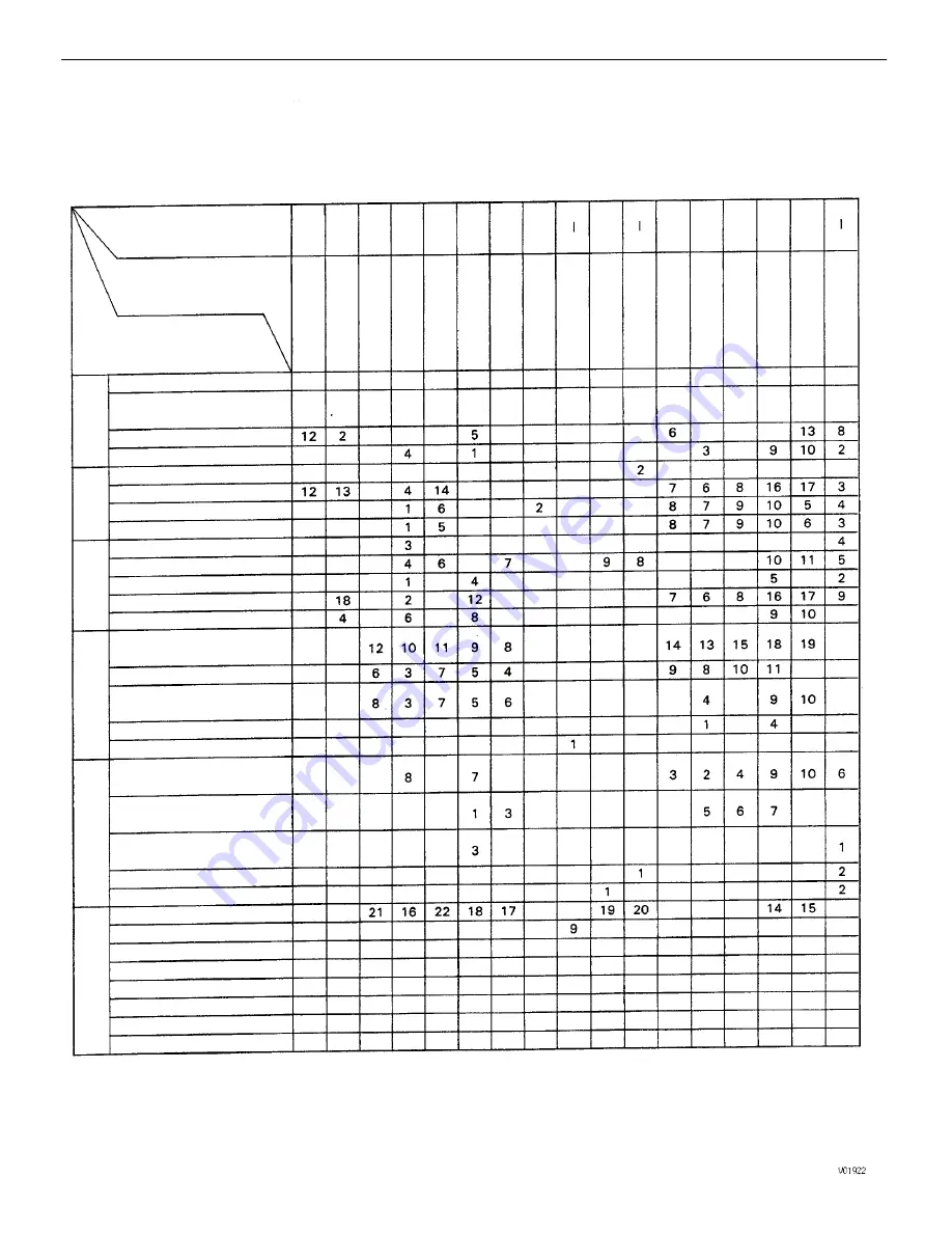
TROUBLESHOOTING
When the malfunction code is not confirmed in the diagnostic code check and the problem still
cannot be confirmed in the basic inspection, then proceed to this step and perform troublesh–
ooting according to the numbers in the order given in the table below.
Starter runs – engine does
not crank
After accelerator pedal
depressed
Engine stall soon after
starting
After accelerator pedal
released
Muffler explosion
rafter fire
Excessive oil consumption
Hesitation
Poor acceleration
(Vv complete combustion
Throttle Position
Sensor Circuit
Heated Oxygen
Sensor Circuit
Intake Air T
emp.
Sensor Circuit
V
olume Air Flow
Meter Circuit
Under normal conditions
High engine idle speed
Battery often discharge
Low engine idle speed
Knock Sensor
Circuit
Engine does not crank
Fuel Pressure
Regulator
Idle Speed
Control V
alve
Starter keeps running
Engine cranks slowly
During A/C operation
No initial combustion
Engine
Coolant
T
e
mp Sensor
Circurt
P
N
P
Signal
Circuit
RPM Signal
Circuit
S
T
A Signal
Circuit
Poor fuel economy
Cold Start
System
A/C Signal
Circuit
When N to D shift
High oil pressure
Incorrect first idle
Engine overcool
Low oil pressure
Engine overheat
Poor drivability
Ignition Circuit
Does not
start
Suspect area
Dif
ficult
to start
Engine stall
Rough idling
Symptom
Cold engine
Fuel Pump
Poor idling
Hot engine
See page
Fuel Lines
injectors
Knocking
Back fire
Surging
EG2–190
EG2–22
o
EG2–199
EG2–160
EG2–18
$
EG2–190
EG2–193
EG2–192
EG2–202
EG2–193
EG2–212
EG2–247
Others
Misfire
IG–16
IG–16
–
ENGINE
ENGINE MECHANICAL
EG2–9
Summary of Contents for 22R-E
Page 1: ...INTRODUCTION INTRODUCTION IN 1 ...
Page 9: ...VEHICLE LIFT AND SUPPORT LOCATIONS INTRODUCTION VEHICLE LIFT AND SUPPORT LOCATIONS IN 9 ...
Page 35: ...22R E ENGINE ENGINE EG1 1 ...
Page 45: ...HINT Adjust idle mixture as necessary ENGINE ENGINE MECHANICAL EG1 11 ...
Page 49: ...CYLINDER HEAD COMPONENTS ENGINE ENGINE MECHANICAL EG1 15 ...
Page 80: ...CYLINDER BLOCK COMPONENTS ENGINE ENGINE MECHANICAL EG1 46 ...
Page 110: ...EXHAUST SYSTEM COMPONENTS ENGINE ENGINE MECHANICAL EG1 76 ...
Page 116: ...LAYOUT AND SCHEMATIC DRAWING Federal and Canada ENGINE EMISSION CONTROL SYSTEMS EG1 82 ...
Page 117: ...LAYOUT AND SCHEMATIC DRAWING Calif ENGINE EMISSION CONTROL SYSTEMS EG1 83 ...
Page 118: ...POSITIVE CRANKCASE VENTILATION PCV SYSTEM ENGINE EMISSION CONTROL SYSTEMS EG1 84 ...
Page 126: ...EXHAUST GAS RECIRCULATION EGR SYSTEM Calif ENGINE EMISSION CONTROL SYSTEMS EG1 92 ...
Page 135: ...MFI SYSTEM DESCRIPTION ENGINE MFI SYSTEM EG1 101 ...
Page 211: ...FUEL PUMP ENGINE MFI SYSTEM EG1 177 ...
Page 226: ...FUEL TANK AND LINE COMPONENTS ENGINE MFI SYSTEM EG1 192 ...
Page 230: ...3 INSTALL INTAKE AIR CONNECTOR ENGINE MFI SYSTEM EG1 196 ...
Page 239: ...2 INSTALL THROTTLE BODY See page EG1 202 ELECTRONIC PARTS LOCATION ENGINE MFI SYSTEM EG1 205 ...
Page 278: ...3VZ E ENGINE ENGINE EG2 1 ...
Page 299: ... ENGINE ENGINE MECHANICAL EG2 22 ...
Page 300: ... ENGINE ENGINE MECHANICAL EG2 23 ...
Page 326: ...CYLINDER HEAD COMPONENTS ENGINE ENGINE MECHANICAL EG2 49 ...
Page 327: ... ENGINE ENGINE MECHANICAL EG2 50 ...
Page 367: ...CYLINDER BLOCK COMPONENTS ENGINE ENGINE MECHANICAL EG2 90 ...
Page 411: ...EXHAUST SYSTEM ENGINE ENGINE MECHANICAL EG2 134 ...
Page 419: ...LAYOUT AND SCHEMATIC DRAWING ENGINE EMISSION CONTROL SYSTEMS EG2 142 ...
Page 435: ...MFI SYSTEM SYSTEM CIRCUIT DESCRIPTION ENGINE MFI SYSTEM EG2 158 ...
Page 476: ... ENGINE MFI SYSTEM EG2 199 ...
Page 497: ...INJECTOR COMPONENTS FOR REMOVAL AND INSTALLATION ENGINE MFI SYSTEM EG2 220 ...
Page 508: ...FUEL TANK AND LINE COMPONENTS ENGINE MFI SYSTEM EG2 231 ...
Page 521: ...ELECTRONIC PARTS LOCATION ENGINE MFI SYSTEM EG2 244 ...
Page 569: ...IGNITION SYSTEM IGNITION SYSTEM IG 1 ...
Page 596: ...STARTING SYSTEM STARTING SYSTEM ST 1 ...
Page 597: ...STARTER COMPONENTS STARTING SYSTEM Starter ST 2 ...
Page 609: ...CHARGING SYSTEM CHARGING SYSTEM CH 1 ...
Page 613: ...GENERATOR COMPONENTS CHARGING SYSTEM Generator CH 5 ...


