13. INSTALL GENERATOR ADJUSTING BAR
14. INSTALL WATER PUMP
(a) . Remove any old packing (FIPG) material and be car–
eful not to drop any oil on the contact surfaces of the
water pump and cylinder block.
•
Using a razor blade and gasket scraper, remove
all the old packing (FIPG) material from the
gasket surfaces and sealing groove.
•
Thoroughly clean all components to remove all
the loose material.
•
Using a non–residue solvent, clean both sealing
surfaces.
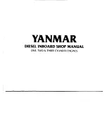
(b) Apply seal packing to the sealing groove of the water
pump as shown in the illustration.
Seal packing:
Part No. 08826–00100 or equivalent
•
Install a nozzle that has been cut to a 2 – 3 mm
(0.08 – 0.12 in.) opening.
•
Parts must be assembled within 5 minutes of
application. Otherwise the material must be re–
moved and reapplied.
•
Immediately remove nozzle from the tube and
reinstall cap.
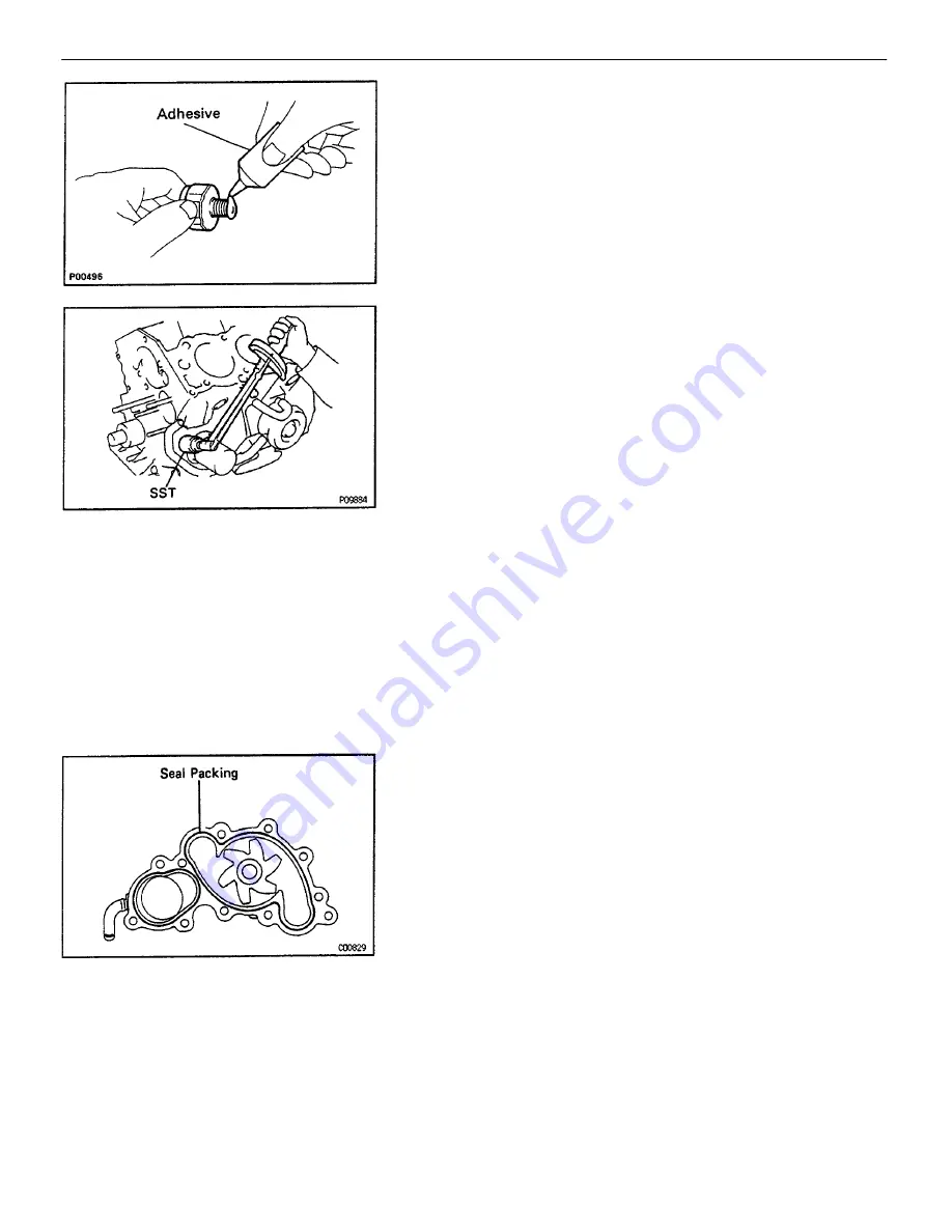
12. INSTALL OIL PRESSURE SENDER GAUGE
(a) Apply adhesive to two or three threads.
Adhesive:
Part No.08833–00080, THREE BOND 1344,
LOCTITE 242 or equivalent
(b) Using SST, install the oil pressure sender gauge.
SST 09816–30010
Torque: 15 N–m (150 kgf–cm. 11 ft–lbf)
–
ENGINE
ENGINE MECHANICAL
EG2–127
Summary of Contents for 22R-E
Page 1: ...INTRODUCTION INTRODUCTION IN 1 ...
Page 9: ...VEHICLE LIFT AND SUPPORT LOCATIONS INTRODUCTION VEHICLE LIFT AND SUPPORT LOCATIONS IN 9 ...
Page 35: ...22R E ENGINE ENGINE EG1 1 ...
Page 45: ...HINT Adjust idle mixture as necessary ENGINE ENGINE MECHANICAL EG1 11 ...
Page 49: ...CYLINDER HEAD COMPONENTS ENGINE ENGINE MECHANICAL EG1 15 ...
Page 80: ...CYLINDER BLOCK COMPONENTS ENGINE ENGINE MECHANICAL EG1 46 ...
Page 110: ...EXHAUST SYSTEM COMPONENTS ENGINE ENGINE MECHANICAL EG1 76 ...
Page 116: ...LAYOUT AND SCHEMATIC DRAWING Federal and Canada ENGINE EMISSION CONTROL SYSTEMS EG1 82 ...
Page 117: ...LAYOUT AND SCHEMATIC DRAWING Calif ENGINE EMISSION CONTROL SYSTEMS EG1 83 ...
Page 118: ...POSITIVE CRANKCASE VENTILATION PCV SYSTEM ENGINE EMISSION CONTROL SYSTEMS EG1 84 ...
Page 126: ...EXHAUST GAS RECIRCULATION EGR SYSTEM Calif ENGINE EMISSION CONTROL SYSTEMS EG1 92 ...
Page 135: ...MFI SYSTEM DESCRIPTION ENGINE MFI SYSTEM EG1 101 ...
Page 211: ...FUEL PUMP ENGINE MFI SYSTEM EG1 177 ...
Page 226: ...FUEL TANK AND LINE COMPONENTS ENGINE MFI SYSTEM EG1 192 ...
Page 230: ...3 INSTALL INTAKE AIR CONNECTOR ENGINE MFI SYSTEM EG1 196 ...
Page 239: ...2 INSTALL THROTTLE BODY See page EG1 202 ELECTRONIC PARTS LOCATION ENGINE MFI SYSTEM EG1 205 ...
Page 278: ...3VZ E ENGINE ENGINE EG2 1 ...
Page 299: ... ENGINE ENGINE MECHANICAL EG2 22 ...
Page 300: ... ENGINE ENGINE MECHANICAL EG2 23 ...
Page 326: ...CYLINDER HEAD COMPONENTS ENGINE ENGINE MECHANICAL EG2 49 ...
Page 327: ... ENGINE ENGINE MECHANICAL EG2 50 ...
Page 367: ...CYLINDER BLOCK COMPONENTS ENGINE ENGINE MECHANICAL EG2 90 ...
Page 411: ...EXHAUST SYSTEM ENGINE ENGINE MECHANICAL EG2 134 ...
Page 419: ...LAYOUT AND SCHEMATIC DRAWING ENGINE EMISSION CONTROL SYSTEMS EG2 142 ...
Page 435: ...MFI SYSTEM SYSTEM CIRCUIT DESCRIPTION ENGINE MFI SYSTEM EG2 158 ...
Page 476: ... ENGINE MFI SYSTEM EG2 199 ...
Page 497: ...INJECTOR COMPONENTS FOR REMOVAL AND INSTALLATION ENGINE MFI SYSTEM EG2 220 ...
Page 508: ...FUEL TANK AND LINE COMPONENTS ENGINE MFI SYSTEM EG2 231 ...
Page 521: ...ELECTRONIC PARTS LOCATION ENGINE MFI SYSTEM EG2 244 ...
Page 569: ...IGNITION SYSTEM IGNITION SYSTEM IG 1 ...
Page 596: ...STARTING SYSTEM STARTING SYSTEM ST 1 ...
Page 597: ...STARTER COMPONENTS STARTING SYSTEM Starter ST 2 ...
Page 609: ...CHARGING SYSTEM CHARGING SYSTEM CH 1 ...
Page 613: ...GENERATOR COMPONENTS CHARGING SYSTEM Generator CH 5 ...


