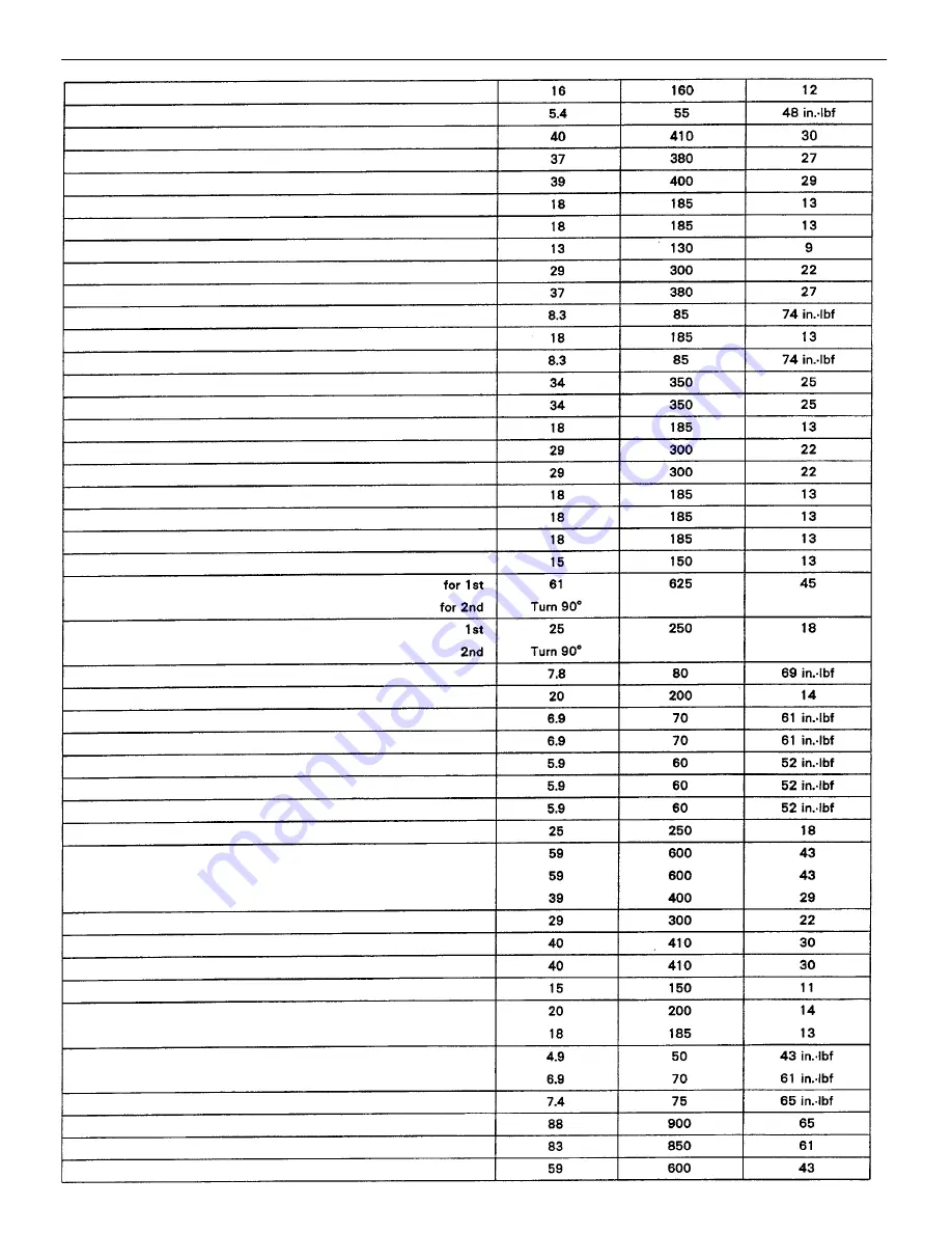
No.1 water by–pass pipe x Cylinder block
for union bolt (2WD)
for relief valve (4WD)
for bolt
No.4 timing belt cover x No.3 timing belt cover
LH engine mounting bracket x Cylinder block
RH engine mounting bracket x Cylinder block
Cold start injector tube x Cold start injector
No.1 injection manifold x Exhaust Manifold
Air intake chamber stay x Air intake chamber
Exhaust crossover pipe x Exhaust Manifold
Oil pressure sender gauge x Cylinder block
Engine coolant drain plug x Cylinder block
Water by–pass outlet x Intake manifold
Air intake chamber stay x Cylinder head
Camshaft bearing cap x Cylinder head
Connecting rod cap x Connecting rod
No.3 timing belt cover x Cylinder head
Cylinder block x Oil cooler relief valve
Rear oil seal retainer x Cylinder block
Cylinder head cover x Cylinder head
Air intake chamber x Intake manifold
No.2 idler pulley x Intake manifold
Oil dipstick guide x Cylinder head
Main bearing cap x Cylinder block
EGR pipe x Air intake chamber
Oil pan x Rear ail seal retainer
PAIR reed valve x Cylinder head
Rear end plate x Cylinder block
Intake manifold x Cylinder head
Engine hanger x Cylinder head
EGR valve x Air intake chamber
Crankshaft x Drive plate (A/T)
Oil strainer x Main bearing cap
Oil filter union x Cylinder block
No.3 fuel pipe x Delivery pipe
No.2 fuel pipe x Delivery pipe
Delivery pipe x Cylinder head
EGR pipe x Exhaust manifold
Water pump x Cylinder block
Crankshaft x Flywheel (M/T)
Oil pump x Cylinder block
Oil cooler x Cylinder block
for short bolt
for long bolt
Oil pan x Cylinder block
Oil strainer x Oil pump
Oil pan x Oil pump
for bolt
for nut
–
ENGINE
ENGINE MECHANICAL
EG2–139
Summary of Contents for 22R-E
Page 1: ...INTRODUCTION INTRODUCTION IN 1 ...
Page 9: ...VEHICLE LIFT AND SUPPORT LOCATIONS INTRODUCTION VEHICLE LIFT AND SUPPORT LOCATIONS IN 9 ...
Page 35: ...22R E ENGINE ENGINE EG1 1 ...
Page 45: ...HINT Adjust idle mixture as necessary ENGINE ENGINE MECHANICAL EG1 11 ...
Page 49: ...CYLINDER HEAD COMPONENTS ENGINE ENGINE MECHANICAL EG1 15 ...
Page 80: ...CYLINDER BLOCK COMPONENTS ENGINE ENGINE MECHANICAL EG1 46 ...
Page 110: ...EXHAUST SYSTEM COMPONENTS ENGINE ENGINE MECHANICAL EG1 76 ...
Page 116: ...LAYOUT AND SCHEMATIC DRAWING Federal and Canada ENGINE EMISSION CONTROL SYSTEMS EG1 82 ...
Page 117: ...LAYOUT AND SCHEMATIC DRAWING Calif ENGINE EMISSION CONTROL SYSTEMS EG1 83 ...
Page 118: ...POSITIVE CRANKCASE VENTILATION PCV SYSTEM ENGINE EMISSION CONTROL SYSTEMS EG1 84 ...
Page 126: ...EXHAUST GAS RECIRCULATION EGR SYSTEM Calif ENGINE EMISSION CONTROL SYSTEMS EG1 92 ...
Page 135: ...MFI SYSTEM DESCRIPTION ENGINE MFI SYSTEM EG1 101 ...
Page 211: ...FUEL PUMP ENGINE MFI SYSTEM EG1 177 ...
Page 226: ...FUEL TANK AND LINE COMPONENTS ENGINE MFI SYSTEM EG1 192 ...
Page 230: ...3 INSTALL INTAKE AIR CONNECTOR ENGINE MFI SYSTEM EG1 196 ...
Page 239: ...2 INSTALL THROTTLE BODY See page EG1 202 ELECTRONIC PARTS LOCATION ENGINE MFI SYSTEM EG1 205 ...
Page 278: ...3VZ E ENGINE ENGINE EG2 1 ...
Page 299: ... ENGINE ENGINE MECHANICAL EG2 22 ...
Page 300: ... ENGINE ENGINE MECHANICAL EG2 23 ...
Page 326: ...CYLINDER HEAD COMPONENTS ENGINE ENGINE MECHANICAL EG2 49 ...
Page 327: ... ENGINE ENGINE MECHANICAL EG2 50 ...
Page 367: ...CYLINDER BLOCK COMPONENTS ENGINE ENGINE MECHANICAL EG2 90 ...
Page 411: ...EXHAUST SYSTEM ENGINE ENGINE MECHANICAL EG2 134 ...
Page 419: ...LAYOUT AND SCHEMATIC DRAWING ENGINE EMISSION CONTROL SYSTEMS EG2 142 ...
Page 435: ...MFI SYSTEM SYSTEM CIRCUIT DESCRIPTION ENGINE MFI SYSTEM EG2 158 ...
Page 476: ... ENGINE MFI SYSTEM EG2 199 ...
Page 497: ...INJECTOR COMPONENTS FOR REMOVAL AND INSTALLATION ENGINE MFI SYSTEM EG2 220 ...
Page 508: ...FUEL TANK AND LINE COMPONENTS ENGINE MFI SYSTEM EG2 231 ...
Page 521: ...ELECTRONIC PARTS LOCATION ENGINE MFI SYSTEM EG2 244 ...
Page 569: ...IGNITION SYSTEM IGNITION SYSTEM IG 1 ...
Page 596: ...STARTING SYSTEM STARTING SYSTEM ST 1 ...
Page 597: ...STARTER COMPONENTS STARTING SYSTEM Starter ST 2 ...
Page 609: ...CHARGING SYSTEM CHARGING SYSTEM CH 1 ...
Page 613: ...GENERATOR COMPONENTS CHARGING SYSTEM Generator CH 5 ...


