background image

2GR-FE ENGINE CONTROL SYSTEM

  –  SFI SYSTEM

ES–25

ES

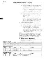
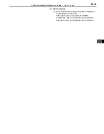
(g) Enter the following menus: DIAGNOSIS / 

ENHANCED OBD ll / VIN.

3.

WRITE VIN

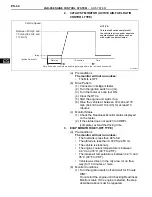
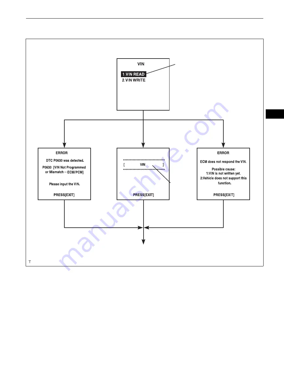
(a) The flowchart of the VIN writing process is shown. 

This process allows the VIN to be input into the 
ECM. If the ECM is changed, or the VINs do not 
match, the VIN can be registered, or overwritten in 
the ECM by following this procedure.

(b) Write VIN using the intelligent tester.
(c) Check the vehicle's VIN.
(d) Connect the intelligent tester to the DLC3.
(e) Turn the ignition switch on (IG).
(f)

Turn the tester on.

Menu Screen:

Select VIN READ

DTC P0630 Set

VIN Previously Stored

VIN Not Stored

[EXIT]

[EXIT]

[EXIT]

To Menu Screen

17-digit VIN 
displayed

A103812E03

Summary of Contents for 2GR-FE

Page 1: ...rt or a blockage remains even after cleaning the air cleaner filter element with compressed air replace it 6 INSPECT VALVE LASH ADJUSTER NOISE a Rev up the engine several times Check that the engine does not emit unusual noises If unusual noises occur warm up the engine and idle it for over 30 minutes Then repeat this procedure HINT If any defects or problems are found during the inspection above ...

Page 2: ...E When checking the ignition timing the transmission should be in neutral HINT Run the engine at 1 000 to 1 300 rpm for 5 seconds and then check that the engine rpm returns to idle speed 6 Disconnect terminals 13 TC and 4 CG of the DLC3 7 Check the ignition timing at idle Ignition timing 12 to 22 BTDC at idle 8 Confirm that the ignition timing moves to the advanced angle side when the engine rpm i...

Page 3: ...ug hole 2 While cranking the engine measure the compression pressure Compression pressure 1 4 MPa 14 kgf cm2 199 psi Minimum pressure 0 98 MPa 10 kgf cm2 142 psi Difference between each cylinder 0 1 MPa 1 0 kgf cm2 15 psi NOTICE Always use a fully charged battery to obtain an engine speed of 250 rpm or more Check the other cylinders compression pressure in the same way This measurement must be don...

Page 4: ...ply with regulations perform troubleshooting in the order given below 1 Check A F sensor and heated oxygen sensor operation 2 See the table below for possible causes and then inspect and repair CO HC Problems Causes Normal High Rough idle 1 Faulty ignitions Incorrect timing Fouled shorted or improperly gapped plugs 2 Incorrect valve clearance 3 Leaks in intake and exhaust valves 4 Leaks in cylinde...

Page 5: ...2GR FE ENGINE MECHANICAL DRIVE BELT EM 5 EM ENGINE 2GR FE ENGINE MECHANICAL DRIVE BELT COMPONENTS V BANK COVER SUB ASSEMBLY V RIBBED BELT FRONT FENDER APRON SEAL RH A134931E01 ...

Page 6: ...4 REMOVE V RIBBED BELT a Using SST release the belt tension by turning the belt tensioner counterclockwise and remove the V ribbed belt from the belt tensioner SST 09249 63010 b While turning the belt tensioner counterclockwise align with its holes and then insert the 5 mm bi hexagon wrench into the holes to fix the V ribbed belt tensioner SST A129622E01 A095070 ...

Page 7: ...ATION 1 INSTALL V RIBBED BELT a Install the V ribbed belt b Using SST turn the belt tensioner counterclockwise and remove the bar SST 09249 63010 c If it is difficult to install the V ribbed belt perform the following procedure 1 Put the V ribbed belt on every pulley except the tensioner pulley as shown in the illustration 2 While releasing the belt tension by turning the belt tensioner counterclo...

Page 8: ...EM 8 2GR FE ENGINE MECHANICAL DRIVE BELT EM 2 INSTALL V BANK COVER SUB ASSEMBLY See page EM 52 3 INSTALL FRONT FENDER APRON SEAL RH 4 INSTALL FRONT WHEEL RH Torque 103 N m 1 050 kgf cm 76 ft lbf ...

Page 9: ... ENGINE 2GR FE ENGINE MECHANICAL ENGINE FRONT OIL SEAL COMPONENTS CRANKSHAFT PULLEY TIMING CHAIN CASE OIL SEAL V BANK COVER SUB ASSEMBLY V RIBBED BELT FRONT FENDER APRON SEAL RH 250 2 550 184 N m kgf cm ft lbf Specified torque Non reusable part A134932E01 ...

Page 10: ...ST 09213 70011 09213 70020 09330 00021 b Using SST remove the crankshaft pulley bolt and crankshaft pulley SST 09950 50013 09951 05010 09952 05010 09953 05020 09954 05021 6 REMOVE TIMING CHAIN CASE OIL SEAL a Using a screwdriver pry out the oil seal HINT Tape the screwdriver tip before use NOTICE After the removal check the crankshaft for damage If it is damaged smooth the surface with 400 grit sa...

Page 11: ...foreign matter Do not tap the oil seal at an angle 2 INSTALL CRANKSHAFT PULLEY a Align the pulley set key with the key groove of the pulley and slide on the pulley b Using SST install the pulley bolt SST 09213 70011 09213 70020 09330 00021 Torque 250 N m 2 550 kgf cm 184 ft lbf 3 INSTALL V RIBBED BELT See page EM 7 4 INSTALL V BANK COVER SUB ASSEMBLY See page EM 52 5 INSTALL FRONT FENDER APRON SEA...

Page 12: ...L SEAL EM 11 EM ENGINE 2GR FE ENGINE MECHANICAL ENGINE REAR OIL SEAL COMPONENTS DRIVE PLATE AND RING GEAR SUB ASSEMBLY ENGINE REAR OIL SEAL FRONT SPACER REAR SPACER N m kgf cm ft lbf Specified torque Non reusable part 83 850 61 x8 A134930E01 ...

Page 13: ...ENGINE REAR OIL SEAL a Using a knife cut off the oil seal lip b Using a screwdriver pry out the oil seal NOTICE Be careful not to damage the crankshaft Tape the screwdriver tip before use INSTALLATION 1 INSTALL ENGINE REAR OIL SEAL a Apply MP grease to a new oil seal lip b Using SST and a hammer tap in the oil seal SST 09223 15030 09950 70010 09951 07150 Oil seal tap in depth 0 5 to 0 5 mm 0 020 t...

Page 14: ...2 or 3 threads of the mounting bolt end Adhesive Part No 08833 00070 THREE BOND 1324 or equivalent 1 Install the front spacer drive plate and rear spacer on the crankshaft 2 Install and tighten the 8 mounting bolts uniformly in several steps Torque 83 N m 850 kgf cm 61 ft lbf 3 INSTALL AUTOMATIC TRANSAXLE ASSEMBLY HINT See page AX 214 SST A129631E01 Adhesive P000601E04 1 7 4 6 2 8 3 5 A132243E01 ...

Page 15: ... BLADE ASSEMBLY RH FRONT WIPER ARM AND BLADE ASSEMBLY LH COWL TOP VENTILATOR LOUVER SUB ASSEMBLY COWL TOP PANEL OUTER SUB ASSEMBLY FRONT FENDER TO COWL SIDE SEAL LH FRONT FENDER TO COWL SIDE SEAL RH 20 204 15 7 5 77 66 in lbf N m kgf cm ft lbf Specified torque 5 0 51 44 in lbf 85 867 63 WINDSHIELD WIPER LINK ASSEMBLY A134938E01 ...

Page 16: ...INTAKE DUCT SEAL INTAKE AIR RESONATOR SUB ASSEMBLY NO 1 AIR CLEANER INLET RELAY BLOCK COVER UPPER V BANK COVER SUB ASSEMBLY 5 0 51 44 in lbf 5 0 51 44 in lbf 5 0 51 44 in lbf 5 0 51 44 in lbf N m kgf cm ft lbf Specified torque 3 5 36 31 in lbf 9 0 92 80 in lbf AIR CLEANER FILTER ELEMENT ENGINE UNDER COVER RH ENGINE UNDER COVER LH BATTERY TRAY A132994E01 ...

Page 17: ...OUNTING STAY RH V RIBBED BELT HEATER INLET WATER HOSE HEATER OUTLET WATER HOSE NO 1 OIL COOLER INLET HOSE NO 1 OIL COOLER OUTLET HOSE CLIP N m kgf cm ft lbf Specified torque Non reusable part 38 388 28 23 235 17 43 438 32 43 438 32 9 8 100 87 in lbf 25 250 18 25 250 18 13 130 9 NO 1 OIL RESERVOIR TO PUMP HOSE NO 1 FUEL PIPE CLAMP NO 1 FUEL VAPOR FEED HOSE NO 1 VACUUM SWITCHING VALVE ASSEMBLY 10 10...

Page 18: ...BRACKET NO 1 EXHAUST PIPE SUPPORT BRACKET 35 360 26 74 755 55 49 500 36 COTTER PIN 8 0 85 71 in lbf 75 765 55 294 3 000 217 GASKET GASKET GASKET 62 632 46 62 632 46 56 571 41 33 337 24 N m kgf cm ft lbf Specified torque Non reusable part 21 214 15 FRONT AXLE HUB NUT LH STEERING SLIDING YOKE FRONT SUSPENSION LOWER NO 1 ARM LH FRONT SPEED SENSOR LH A132996E01 ...

Page 19: ...UEL PIPE CLAMP N m kgf cm ft lbf Specified torque 95 969 70 95 969 70 87 887 64 37 380 26 37 380 26 32 329 24 32 329 24 32 329 24 32 329 24 32 329 24 85 867 63 85 867 63 85 867 63 85 867 63 32 329 24 FRAME SIDE RAIL PLATE LH FRAME SIDE RAIL PLATE RH FRONT SUSPENSION MEMBER BRACE REAR RH FRONT SUSPENSION MEMBER BRACE REAR LH 9 8 100 87 in lbf 7 8 80 69 in lbf 43 439 32 A134929E01 ...

Page 20: ...BLY RH N m kgf cm ft lbf Specified torque Non reusable part 7 8 80 69 in lbf 64 653 47 46 469 34 43 438 32 41 413 30 64 653 47 64 650 47 54 551 40 DRIVE SHAFT BEARING BRACKET HOLE SNAP RING NO 1 DRIVE SHAFT BEARING BRACKET SETTING BOLT FRONT DRIVE SHAFT INNER LH SHAFT SNAP RING AUTOMATIC TRANSAXLE ASSEMBLY ENGINE MOUNTING BRACKET FR FLYWHEEL HOUSING UNDER COVER EXHAUST PIPE SUPPORT BRACKET 32 334 ...

Page 21: ...55 48 in lbf 21 214 15 21 214 15 21 214 15 16 163 12 18 184 13 NO 1 SURGE TANK STAY VACUUM HOSE CLAMP INTAKE AIR SURGE TANK AIR SURGE TANK TO INTAKE MANIFOLD GASKET UNION TO CHECK VALVE HOSE THROTTLE BODY BRACKET VENTILATION HOSE NO 3 WATER BY PASS HOSE NO 2 WATER BY PASS HOSE x4 DO NOT apply oil A134939E01 ...

Page 22: ... WATER PUMP PULLEY IGNITION COIL ASSEMBLY N m kgf cm ft lbf Specified torque Non reusable part 8 5 87 75 in lbf 8 5 87 75 in lbf 21 214 15 21 214 15 43 438 32 43 438 32 43 438 32 21 214 15 10 102 7 10 102 7 34 347 25 EXHAUST MANIFOLD TO HEAD LH GASKET EXHAUST MANIFOLD TO HEAD GASKET x6 x6 PLATE PLATE NO 2 IDLER PULLEY SUB ASSEMBLY RR SIDE NO 2 IDLER PULLEY SUB ASSEMBLY FR SIDE NO 2 MANIFOLD STAY A...

Page 23: ...15 21 214 15 83 846 61 20 200 14 20 204 15 21 214 15 33 337 24 33 337 24 Precoated Part O RING GASKET NO 1 OIL LEVEL GAUGE GUIDE NO 2 OIL LEVEL GAUGE GUIDE OIL LEVEL GAUGE DRIVE PLATE SPACER FRONT DRIVE PLATE SPACER REAR NO 2 ENGINE HANGER NO 1 ENGINE HANGER NO 2 INTAKE MANIFOLD TO HEAD GASKET NO 1 INTAKE MANIFOLD TO HEAD GASKET ENGINE COOLANT TEMPERATURE SENSOR KNOCK CONTROL SENSOR NO 2 TIMING GE...

Page 24: ...TRANSAXLE FLUID See page AX 207 11 REMOVE WINDSHIELD WIPER LINK ASSEMBLY See page WW 9 12 REMOVE COWL TOP PANEL OUTER SUB ASSEMBLY See page ES 481 13 REMOVE COOL AIR INTAKE DUCT SEAL a Remove the 7 clips and intake duct seal 14 REMOVE V BANK COVER SUB ASSEMBLY a Hold the front of the V bank cover and raise it to disengage the 2 clips on the front of the cover Continue to raise the cover to disenga...

Page 25: ...SEMBLY See page ES 503 18 REMOVE AIR CLEANER CASE SUB ASSEMBLY a Disconnect the vacuum hose and hose clamp b Remove the 3 bolts and air cleaner case 19 REMOVE NO 1 AIR CLEANER INLET a Remove the bolt and No 1 air cleaner inlet 20 REMOVE BATTERY a Loosen the bolt and nut and remove the battery clamp b Remove the battery and battery tray A132969 A132971 A132970 A132972 ...

Page 26: ...t 2 nuts and No 2 mounting stay RH 23 REMOVE ENGINE MOVING CONTROL ROD SUB ASSEMBLY a Remove the 4 bolts and engine moving control rod 24 DISCONNECT NO 1 FUEL VAPOR FEED HOSE a Remove the clamp and disconnect the No 1 fuel vapor feed hose 25 DISCONNECT CHECK VALVE TO BRAKE BOOSTER HOSE a Remove the clamp and disconnect the check valve to brake booster hose A133928 A132985 A132986 A132983 A132982 ...

Page 27: ...1 OIL COOLER INLET HOSE a Remove the clamp and disconnect the oil cooler inlet hose 29 DISCONNECT NO 1 OIL COOLER OUTLET HOSE a Remove the clamp and disconnect the oil cooler outlet hose 30 DISCONNECT HEATER INLET WATER HOSE a Disconnect the heater inlet water hose 31 DISCONNECT HEATER OUTLET WATER HOSE a Disconnect the heater outlet water hose 32 REMOVE ECM HINT See page ES 518 33 REMOVE RELAY BL...

Page 28: ...wire harness 2 Using a screwdriver unlock the engine room J B Pull the engine room J B upward 3 Disconnect the engine wire connectors b Remove the 2 bolts and 2 clamps from the body c Remove the bolt and clamp from the bracket 35 DISCONNECT TRANSMISSION CONTROL CABLE ASSEMBLY a Remove the clip and nut and separate the cable from the transaxle A132975 A132976 A132981 A132973 ...

Page 29: ... together push and pull the connector until it becomes free Put the pipe and connector ends in vinyl bags to prevent damage and contamination 37 DISCONNECT NO 1 OIL RESERVOIR TO PUMP HOSE a Disconnect the No 1 oil reservoir to pump hose 38 DISCONNECT RETURN TUBE SUB ASSEMBLY a Disconnect the return tube sub assembly 39 REMOVE EXHAUST PIPE NO 1 SUPPORT BRACKET See page EX 3 40 REMOVE EXHAUST PIPE A...

Page 30: ...R NO 1 ARM RH HINT Use the same procedures described for the LH side 51 SEPARATE FRONT AXLE ASSEMBLY LH See page DS 8 52 SEPARATE FRONT AXLE ASSEMBLY RH HINT Use the same procedures described for the LH side 53 REMOVE NO 1 EXHAUST PIPE SUPPORT BRACKET a Remove the No 1 exhaust pipe support bracket with the 2 bolts 54 REMOVE DRIVE PLATE AND TORQUE CONVERTER CLUTCH SETTING BOLT See page AX 211 55 DI...

Page 31: ...he power steering oil pressure switch connector b Remove the pressure feed tube clamp bolt c Loosen the bolt A d Remove the bolt B and vane pump 60 INSTALL ENGINE HANGERS a Install the 2 engine hangers with the 4 bolts as shown in the illustration Part No No 1 Engine hanger 12281 31070 No 2 Engine hanger 12282 31050 Bolts 91671 10825 Torque 33 N m 337 kgf cm 24 ft lbf b Attach the engine sling dev...

Page 32: ...STARTER ASSEMBLY See page ST 141 66 REMOVE AUTOMATIC TRANSAXLE ASSEMBLY HINT See page AX 207 67 REMOVE DRIVE PLATE AND RING GEAR SUB ASSEMBLY See page EM 12 68 SECURE ENGINE a Secure the engine onto an engine stand with the bolts 69 REMOVE INTAKE AIR SURGE TANK ASSEMBLY a Disconnect the 2 water by pass hoses from the throttle with motor body assembly b Disconnect the vapor feed hose c Disconnect t...

Page 33: ...ake air surge tank 70 REMOVE IGNITION COIL ASSEMBLY a Remove the 6 bolts and 6 ignition coils 71 REMOVE NO 2 ENGINE MOUNTING STAY RH a Remove the bolt and No 2 engine mounting stay RH 72 REMOVE INTAKE MANIFOLD a Uniformly loosen and remove the 6 bolts and 4 nuts b Remove the intake manifold and 2 gaskets 73 REMOVE EXHAUST MANIFOLD SUB ASSEMBLY RH a Disconnect the A F sensor connector clamp b Unifo...

Page 34: ...el gauge guide 75 REMOVE NO 2 MANIFOLD STAY a Remove the 2 bolts and No 2 manifold stay 76 REMOVE NO 2 EXHAUST MANIFOLD HEAT INSULATOR a Remove the 3 bolts and No 2 insulator 77 REMOVE EXHAUST MANIFOLD SUB ASSEMBLY LH a Uniformly loosen and remove the 6 nuts b Remove the manifold and gasket 78 REMOVE ENGINE MOUNTING BRACKET RH a Remove the 3 bolts and engine mounting bracket RH A129638 A129639 A12...

Page 35: ...ED BELT TENSIONER ASSEMBLY a Remove the 5 bolts and V ribbed belt tensioner assembly 81 REMOVE NO 2 TIMING GEAR COVER a Remove the 2 bolts and No 2 timing gear cover 82 REMOVE NO 2 IDLER PULLEY SUB ASSEMBLY a Remove the bolt plate and No 2 idler pulley sub assembly 83 REMOVE WATER PUMP PULLEY See page CO 8 A129643 A129644 A132987 FR Side RR Side A129645E01 ...

Page 36: ...IO SETTING CONDENSER a Remove the 2 bolts and 2 radio setting condensers 86 REMOVE NO 1 VACUUM SWITCHING VALVE ASSEMBLY a Remove the bolt and No 1 vacuum switching valve 87 REMOVE ENGINE OIL PRESSURE SWITCH ASSEMBLY a Using a 24 mm deep socket wrench remove the engine oil pressure switch assembly 88 REMOVE KNOCK CONTROL SENSOR See page ES 511 A129646 A132991 A132992 A129647 ...

Page 37: ... warpage is greater than the maximum replace the manifold 2 INSPECT EXHAUST MANIFOLD SUB ASSEMBLY RH a Using a precision straightedge and feeler gauge measure the warpage on the contact surface of the cylinder head Maximum warpage 0 7 mm 0 028 in HINT The maximum allowable warpage of each installation surface is 0 3 mm 0 012 in If the warpage is greater than the maximum replace the manifold 3 INSP...

Page 38: ...ifold INSTALLATION 1 INSTALL ENGINE COOLANT TEMPERATURE SENSOR a Using a 19 mm deep socket wrench install the engine coolant temperature sensor and a new gasket Torque 20 N m 200 kgf cm 14 ft lbf 2 INSTALL KNOCK CONTROL SENSOR See page ES 511 3 INSTALL ENGINE OIL PRESSURE SWITCH ASSEMBLY a Clean the threads of the oil pressure switch Apply adhesive to 2 or 3 threads of the oil pressure switch Adhe...

Page 39: ...m 102 kgf cm 7 ft lbf 5 INSTALL RADIO SETTING CONDENSER a Install the 2 bolts and 2 radio setting condensers Torque 10 N m 102 kgf cm 7 ft lbf 6 INSTALL NO 1 ENGINE MOUNTING BRACKET FRONT LH a Install the No 1 engine mounting bracket front LH with the 6 bolts Torque 54 N m 551 kgf cm 40 ft lbf 7 INSTALL WATER PUMP PULLEY See page CO 10 A132992 A132991 A129646 ...

Page 40: ...lts Torque 6 0 N m 61 kgf cm 53 in lbf 10 INSTALL V RIBBED BELT TENSIONER ASSEMBLY a Temporarily install the V ribbed belt tensioner with the 5 bolts HINT Each bolt length is as follows A 70 mm 2 76 in B 33 mm 1 30 in b Install the V ribbed belt tensioner by tightening the bolt 1 and bolt 2 in the order shown in the illustration Torque 43 N m 438 kgf cm 32 ft lbf c Tighten the other bolts Torque 4...

Page 41: ...mounting bracket RH with the 3 bolts Torque 54 N m 551 kgf cm 40 ft lbf 13 INSTALL EXHAUST MANIFOLD SUB ASSEMBLY LH a Install a new gasket as shown in the illustration b Install the exhaust manifold sub assembly LH with the 6 nuts Torque 21 N m 214 kgf cm 15 ft lbf 14 INSTALL NO 2 EXHAUST MANIFOLD HEAT INSULATOR a Install the No 2 insulator with the 3 bolts Torque 8 5 N m 87 kgf cm 75 in lbf A1296...

Page 42: ...N m 214 kgf cm 15 ft lbf e Install the oil level gauge guide No 2 with the bolt Torque 21 N m 214 kgf cm 15 ft lbf f Install the oil level gauge 17 INSTALL EXHAUST MANIFOLD SUB ASSEMBLY RH a Install a new gasket as shown in the illustration b Install the exhaust manifold sub assembly RH with the 6 nuts Torque 21 N m 214 kgf cm 15 ft lbf 18 INSTALL INTAKE MANIFOLD a Set a new gasket on each cylinde...

Page 43: ... oil to the bolts as listed below a Install a new gasket to the intake air surge tank b Using a 5 mm hexagon socket wrench install the 4 bolts and 2 nuts Torque Bolt 18 N m 184 kgf cm 13 ft lbf Nut 16 N m 163 kgf cm 12 ft lbf c Install the throttle body bracket No 1 surge tank stay and 4 bolts Torque 21 N m 214 kgf cm 15 ft lbf d Connect the connector Tightening Parts Torque N m kgf cm ft lbf QTY ...

Page 44: ...LL DRIVE PLATE AND RING GEAR SUB ASSEMBLY See page EM 13 24 INSTALL AUTOMATIC TRANSAXLE ASSEMBLY HINT See page AX 214 25 INSTALL STARTER ASSEMBLY See page ST 148 26 INSTALL ENGINE WIRE 27 INSTALL FRONT DRIVE SHAFT ASSEMBLY LH See page DS 20 28 INSTALL FRONT DRIVE SHAFT ASSEMBLY RH See page DS 21 29 INSTALL FRONT FRAME ASSEMBLY a Install the engine mounting insulators RH and LH with the 2 nuts Torq...

Page 45: ...ressure switch connector 31 INSTALL ENGINE ASSEMBLY WITH TRANSAXLE a Set the engine assembly with transaxle on the engine lifter b Install the engine assembly to the vehicle c Install the frame side rail plates RH and LH with the 4 bolts and 2 nuts Torque A 85 N m 867 kgf cm 63 ft lbf B 32 N m 329 kgf cm 24 ft lbf d Install the front suspension member brace rear RH and LH with the 4 bolts and 2 nu...

Page 46: ...ASSEMBLY LH See page DS 21 38 INSTALL FRONT AXLE ASSEMBLY RH HINT Use the same procedures described for the LH side 39 INSTALL FRONT SUSPENSION LOWER NO 1 ARM LH See page DS 21 40 INSTALL FRONT SUSPENSION LOWER NO 1 ARM RH HINT Use the same procedures described for the LH side 41 INSTALL TIE ROD ASSEMBLY LH See page DS 21 42 INSTALL TIE ROD ASSEMBLY RH HINT Use the same procedures described for th...

Page 47: ...sub assembly 53 CONNECT FUEL TUBE SUB ASSEMBLY a Push in the fuel tube connector to the fuel pipe until the connector makes a click sound NOTICE Check for damage or contamination on the connected part of the pipe Check if the pipe and the connector are securely connected by trying to pull them apart b Install the No 1 fuel pipe clamp 54 CONNECT TRANSMISSION CONTROL CABLE ASSEMBLY a Install the cli...

Page 48: ... 9 ft lbf Bolt B 8 4 N m 85 kgf cm 74 in lbf c Connect the wire to the engine room junction block Then install it with the nut and 3 connectors Torque 8 4 N m 85 kgf cm 74 in lbf 56 INSTALL RELAY BLOCK COVER UPPER 57 INSTALL ECM See page ES 519 58 CONNECT HEATER INLET WATER HOSE a Connect the heater inlet water hose 59 CONNECT HEATER OUTLET WATER HOSE a Connect the heater outlet water hose A132981...

Page 49: ...et hose 62 INSTALL RADIATOR HOSE INLET a Install the clamp and connect the radiator hose inlet 63 INSTALL RADIATOR HOSE OUTLET a Install the clamp and connect the radiator hose outlet 64 CONNECT CHECK VALVE TO BRAKE BOOSTER HOSE a Install the clamp and connect the check valve to brake booster hose 65 CONNECT NO 1 FUEL VAPOR FEED HOSE a Install the clamp and connect the No 1 fuel vapor feed hose A1...

Page 50: ...que 38 N m 388 kgf cm 28 ft lbf b Tighten the 2 nuts Torque 23 N m 235 kgf cm 17 ft lbf 68 INSTALL INTAKE AIR RESONATOR SUB ASSEMBLY a Install the intake air resonator with the bolt and clip Torque 5 0 N m 51 kgf cm 44 in lbf 69 INSTALL BATTERY a Install the battery and battery tray b Install the battery clamp with the bolt and nut Torque Bolt 9 0 N m 92 kgf cm 80 in lbf Nut 3 5 N m 36 kgf cm 31 i...

Page 51: ... cleaner case with the 3 bolts Torque 5 0 N m 51 kgf cm 44 in lbf b Connect the vacuum hose and hose clamp 72 INSTALL AIR CLEANER CAP SUB ASSEMBLY See page ES 506 73 INSTALL AIR CLEANER INLET ASSEMBLY a Install the air cleaner inlet with the clamp and 2 bolts Torque 5 0 N m 51 kgf cm 44 in lbf A132971 A132969 ...

Page 52: ...WHEELS Torque 103 N m 1 050 kgf cm 76 ft lbf 79 ADD ENGINE OIL 80 CONNECT CABLE TO NEGATIVE BATTERY TERMINAL Torque 6 9 N m 70 kgf cm 61 in lbf 81 ADD ENGINE COOLANT See page CO 6 82 ADD AUTOMATIC TRANSAXLE FLUID See page AX 220 83 ADD POWER STEERING FLUID Vacuum Hose Routing Diagram Intake Air Surge Tank VSV VSV Actuator VSV for Active Control Engine Mount ACM Engine Mounting Insulator FR Air Cle...

Page 53: ...NITION TIMING See page EM 1 92 CHECK ENGINE IDLE SPEED See page EM 2 93 CHECK CO HC See page EM 4 94 CHECK FUNCTION OF THROTTLE BODY See page ES 503 95 INSTALL FRONT FENDER APRON SEAL RH 96 INSTALL ENGINE UNDER COVER LH 97 INSTALL ENGINE UNDER COVER RH 98 INSTALL V BANK COVER SUB ASSEMBLY a Fit the 3 retainers and install the V bank cover 99 INSTALL COOL AIR INTAKE DUCT SEAL a Install the intake d...

Page 54: ...PLUG 10 102 7 18 184 13 10 102 7 10 102 7 CAMSHAFT POSITION SENSOR 10 102 7 10 102 7 CYLINDER HEAD COVER GASKET x3 SEAL WASHER 21 214 15 CAMSHAFT POSITION SENSOR 10 102 7 GASKET GASKET 65 663 48 OIL CONTROL VALVE FILTER RH x9 RH SIDE O RING O RING CYLINDER HEAD COVER SUB ASSEMBLY CAMSHAFT TIMING OIL CONTROL VALVE ASSEMBLY 10 102 7 65 663 48 OIL PIPE A132493E01 ...

Page 55: ... Precoated part 27 275 20 N m kgf cm ft lbf Specified torque Non reusable part GASKET GASKET OIL CONTROL VALVE FILTER LH CYLINDER HEAD COVER GASKET x8 21 214 15 10 102 7 10 102 7 10 102 7 18 184 13 OIL FILLER CAP GASKET O RING O RING 10 102 7 SEAL WASHER LH SIDE x3 10 102 7 CYLINDER HEAD COVER SUB ASSEMBLY CAMSHAFT TIMING OIL CONTROL VALVE ASSEMBLY 65 663 48 10 102 7 A132494E01 ...

Page 56: ...LINDER BLOCK WATER DRAIN COCK PLUG CYLINDER BLOCK WATER DRAIN COCK PLUG 25 255 18 13 130 9 25 255 18 13 130 9 GASKET O RING 10 102 7 x4 x2 ENGINE REAR OIL SEAL ENGINE REAR OIL SEAL RETAINER GASKET WATER INLET HOUSING WATER OUTLET O RING 10 102 7 x4 x2 10 103 7 x2 10 102 7 WATER INLET THERMOSTAT x2 10 102 7 DRAIN COCK PLUG DRAIN COCK ASSEMBLY 13 130 9 30 306 22 FRONT ENGINE MOUNTING BRACKET NO 1 LH...

Page 57: ...08 30 N m kgf cm ft lbf Specified torque Non reusable part 10 102 7 x7 10 102 7 GASKET 10 102 7 O RING 21 214 15 25 255 18 OIL FILTER CAP SUB ASSEMBLY O RING 21 214 15 10 102 7 10 102 7 10 102 7 OIL PAN DRAIN PLUG GASKET x14 x16 OIL PAN BAFFLE PLATE 21 214 15 DRAIN PLUG 21 214 15 x2 4 0 41 35 in lbf 10 102 7 10 102 7 4 0 41 35 in lbf 4 0 41 35 in lbf A132496E01 ...

Page 58: ...1 93 81 in lbf 9 1 93 81 in lbf 21 214 15 N m kgf cm ft lbf Specified torque Non reusable part WATER PUMP GASKET 21 214 15 x6 x8 x4 250 2 550 184 43 438 32 21 214 15 x10 9 1 93 81 in lbf CHAIN COVER PLATE CHAIN COVER PLATE GASKET x4 TIMING CHAIN CASE OIL SEAL TIMING CHAIN COVER SUB ASSEMBLY A132497E01 ...

Page 59: ...PPER IDLE SPROCKET ASSEMBLY NO 1 CHAIN TENSIONER ASSEMBLY NO 1 CHAIN VIBRATION DAMPER NO 2 CHAIN VIBRATION DAMPER 23 230 17 N m kgf cm ft lbf Specified torque Non reusable part 10 102 7 GASKET KEY NO 1 IDLE GEAR SHAFT 60 612 44 NO 2 IDLE GEAR SHAFT CRANKSHAFT TIMING SPROCKET A132498E01 ...

Page 60: ... 286 21 N m kgf cm ft lbf Specified torque Non reusable part 100 1 020 74 x12 x12 NO 2 CHAIN TENSIONER ASSEMBLY 28 286 21 21 214 15 CAMSHAFT TIMING EXHAUST GEAR ASSEMBLY RH CAMSHAFT TIMING GEAR ASSEMBLY NO 2 CHAIN SUB ASSEMBLY GASKET GASKET CAMSHAFT BEARING CAP 28 286 21 1st 10 102 7 2nd 16 163 12 RH SIDE x8 NO 2 CAMSHAFT CAMSHAFT x8 A132499E01 ...

Page 61: ...VE LASH ADJUSTER ASSEMBLY 21 214 15 N m kgf cm ft lbf Specified torque Non reusable part 100 1 020 74 1st 10 102 7 2nd 16 163 12 28 286 21 28 286 21 CAMSHAFT TIMING EXHAUST GEAR ASSEMBLY LH CAMSHAFT TIMING GEAR ASSEMBLY NO 2 CHAIN SUB ASSEMBLY CAMSHAFT BEARING CAP GASKET GASKET 28 286 21 LH SIDE x12 x12 x8 x8 NO 3 CAMSHAFT NO 4 CAMSHAFT A132500E01 ...

Page 62: ... RH 10 102 7 N m kgf cm ft lbf Specified torque Non reusable part 1st 36 367 27 NO 2 CYLINDER HEAD GASKET CYLINDER HEAD GASKET 30 306 22 2nd Turn 90 3rd Turn 90 PLATE WASHER 1st 36 367 27 2nd Turn 90 3rd Turn 90 PLATE WASHER x8 x8 x8 x8 x2 CLAMP NO 1 WATER BY PASS HOSE WATER INLET PIPE CLAMP A132501E01 ...

Page 63: ...44 449 32 GASKET VALVE SPRING RETAINER LOCK INNER COMPRESSION SPRING VALVE SPRING RETAINER VALVE SPRING RETAINER LOCK INNER COMPRESSION SPRING VALVE SPRING RETAINER GASKET VALVE STEM OIL SEAL EXHAUST VALVE GUIDE BUSH INTAKE VALVE GUIDE BUSH VALVE SPRING SEAT VALVE STEM CAP VALVE SPRING SEAT VALVE STEM CAP RING PIN STRAIGHT PIN STUD BOLT STUD BOLT 4 0 41 35 in lbf 10 102 7 x2 STUD BOLT 10 102 7 A13...

Page 64: ...D CAP SEAL WASHER CYLINDER BLOCK SUB ASSEMBLY LOWER CRANKSHAFT BEARING UPPER CRANKSHAFT BEARING UPPER CRANKSHAFT THRUST WASHER CRANKSHAFT BEARING CAP x8 x8 9 0 92 80 in lbf 52 525 38 N m kgf cm ft lbf Specified torque Non reusable part 1st 61 622 45 2nd Turn 90 SEAL WASHER 1st 25 255 18 2nd Turn 90 52 525 38 x4 x4 x4 x4 x4 STRAIGHT PIN STUD BOLT STRAIGHT PIN x4 x4 STRAIGHT PIN x2 x2 10 102 7 STRAI...

Page 65: ... filler cap and gasket 2 REMOVE SPARK PLUG a Remove the spark plugs 3 REMOVE OIL PAN DRAIN PLUG a Remove the drain plug and gasket 4 REMOVE VENTILATION VALVE SUB ASSEMBLY a Remove the ventilation valve 5 REMOVE CAMSHAFT POSITION SENSOR a Remove the 4 bolts and 4 sensors A129654 A129655 LH Bank RH Bank A129656E01 ...

Page 66: ... the bolt and sensor 8 REMOVE NO 1 OIL PIPE a Remove the 2 oil pipe unions and oil pipe b Remove the oil control valve filter LH and gaskets 9 REMOVE OIL PIPE a Remove the bolt b Remove the 2 oil pipe unions and oil pipe c Remove the oil control valve filter RH and gaskets LH Bank RH Bank A129662E01 A129663 Oil Pipe Union Oil Pipe Union A135726E01 Oil Pipe Union Oil Pipe Union A134878E01 ...

Page 67: ...ock plugs from the water drain cocks 11 REMOVE OIL FILTER ELEMENT a Remove the drain plug NOTICE Do not remove the O ring from the oil filter cap b Connect the hose to the pipe c Insert the pipe with the hose into the oil filter cap d Make sure that the oil is completely drained and remove the pipe and O ring RH Side LH Side A135829E01 A129666 Pipe O Ring Pipe Hose Hose A129667E01 ...

Page 68: ...g the O ring to prevent the O ring groove from being damaged 12 REMOVE CRANKSHAFT PULLEY a Using SST loosen the crankshaft pulley bolt SST 09213 70011 09213 70020 09330 00021 b Using SST remove the crankshaft pulley bolt and crankshaft pulley SST 09950 50013 09951 05010 09952 05010 09953 05020 09954 05021 SST A129668E01 Oil Filter Element O Ring A106167E01 SST Turn Hold A120690E02 SST Turn Hold A1...

Page 69: ...ER INLET HOUSING a Remove the 2 nuts water inlet and thermostat b Remove the gasket c Remove the housing plug d Remove the housing drain cock e Remove the 2 stud bolts f Separate the water by pass hose No 1 g Remove the 2 bolts nut and water inlet housing h Remove the 2 O rings 15 REMOVE WATER OUTLET a Remove the 2 bolts 4 nuts and water outlet A129672 A129673 Nut A134879E01 A129675 Nut Nut Nut Nu...

Page 70: ...over and gasket b Remove the 3 gaskets 17 REMOVE CYLINDER HEAD COVER SUB ASSEMBLY for Bank 2 a Remove the 12 bolts seal washer head cover and gasket NOTICE The baffle plate is located on the back of the portion shown in the illustration Do not damage the baffle plate when removing the head cover b Remove the 3 gaskets A129677 A129679 A129699 Baffle Plate A129678E02 A129705 ...

Page 71: ... not to damage the contact surfaces of the oil pans c Using Torx socket wrench E6 remove the 2 stud bolts 19 REMOVE OIL STRAINER SUB ASSEMBLY a Remove the bolt 2 nuts oil strainer and gasket b Using Torx socket wrench E6 remove the 2 stud bolts 20 REMOVE OIL PAN SUB ASSEMBLY a Remove the 16 bolts and 2 nuts HINT Be sure to clean the bolts and stud bolts and check the threads for cracks or other da...

Page 72: ...the contact surfaces of the cylinder block and oil pan HINT Tape the screwdriver tip before use c Remove the 2 O rings d Using Torx socket wrench E8 remove the 2 stud bolts 21 REMOVE OIL PAN BAFFLE PLATE a Remove the 7 bolts and baffle plate 22 REMOVE ENGINE REAR OIL SEAL RETAINER a Remove the 6 bolts Protective Tape Protective Tape A129683E01 A129684 A129685 A129686 ...

Page 73: ...the oil seal retainer on wooden blocks NOTICE Be careful not to damage the engine rear oil seal retainer b Using a screwdriver and a hammer tap out the oil seal HINT Tape the screwdriver tip before use 24 REMOVE WATER PUMP ASSEMBLY a Remove the 16 bolts water pump and gasket 25 REMOVE TIMING CHAIN COVER SUB ASSEMBLY a Remove the 15 bolts and 2 nuts as shown in the illustration Pry A129687E01 Woode...

Page 74: ...e c Remove the 4 bolts chain cover plate and gasket d Remove the gasket 26 REMOVE TIMING CHAIN CASE OIL SEAL a Using a screwdriver pry out the oil seal HINT Tape the screwdriver tip before use 27 SET NO 1 CYLINDER TO TDC COMPRESSION a Temporarily tighten the pulley set bolt b Set the timing mark on the crank angle sensor plate to the RH block bore center line TDC compression Protective Tape Protec...

Page 75: ... above 28 REMOVE NO 1 CHAIN TENSIONER ASSEMBLY a Move the stopper plate upward to release the lock and push the plunger deep into the tensioner b Move the stopper plate downward to set the lock and insert a pin of φ1 27 mm 0 05 in into the stopper plate s hole c Remove the 2 bolts and chain tensioner 29 REMOVE CHAIN TENSIONER SLIPPER a Remove the chain tensioner slipper Timing Marks Timing Marks A...

Page 76: ...ly on the RH bank clockwise approximately 60 and set it as shown in the illustration Be sure to loosen the chain between the banks e Remove the chain 31 REMOVE IDLE SPROCKET ASSEMBLY a Using a 10 mm hexagon wrench remove the No 2 idle gear shaft sprocket and No 1 idle gear shaft 32 REMOVE NO 1 CHAIN VIBRATION DAMPER a Remove the 2 bolts and vibration damper 33 REMOVE NO 2 CHAIN VIBRATION DAMPER a ...

Page 77: ... insert a pin of φ 1 0 mm 0 039 in into the hole to fix the No 2 chain tensioner b Hold the hexagonal portion of the camshaft with a wrench and remove the 2 bolts and 2 camshaft timing gear assemblies NOTICE Be careful not to damage the cylinder head with the wrench Do not disassemble the camshaft timing gear assemblies c Remove the No 2 chain 36 REMOVE NO 2 CHAIN TENSIONER ASSEMBLY a Remove the b...

Page 78: ...e sequence shown in the illustration c Uniformly loosen and remove the 12 bearing cap bolts in the sequence shown in the illustration NOTICE Uniformly loosen the bolts while keeping the camshaft level d Remove the 5 bearing caps 38 REMOVE CAMSHAFT a Remove the camshaft 39 REMOVE NO 2 CAMSHAFT a Remove the No 2 camshaft Front View Knock Pin 45 A129700E01 1 3 4 5 6 7 8 2 A129701E03 5 6 4 1 10 12 11 ...

Page 79: ... before use 41 REMOVE CAMSHAFT TIMING GEARS AND NO 2 CHAIN for Bank 2 a While pushing down the No 3 chain tensioner insert a pin of φ 1 0 mm 0 039 in into the hole to fix the No 3 chain tensioner b Hold the hexagonal portion of the camshaft with a wrench and remove the 2 bolts and 2 camshaft timing gear assemblies NOTICE Be careful not to damage the cylinder head with the wrench Do not disassemble...

Page 80: ...ve the 8 bearing cap bolts in the sequence shown in the illustration c Uniformly loosen and remove the 13 bearing cap bolts in the sequence shown in the illustration NOTICE Uniformly loosen the bolts while keeping the camshaft level d Remove the 5 bearing caps 44 REMOVE NO 3 CAMSHAFT a Remove the No 3 camshaft 45 REMOVE NO 4 CAMSHAFT a Remove the No 4 camshaft A109722 Front View Knock Pin A129706E...

Page 81: ...om the cylinder head HINT Arrange the removed parts in the correct order 49 REMOVE CYLINDER HEAD SUB ASSEMBLY RH a Using a 10 mm bi hexagon wrench uniformly loosen the 8 bolts in the sequence shown in the illustration Remove the 8 cylinder head bolts and plate washers NOTICE Be careful not to drop washers into the cylinder head Cylinder head warpage or cracking could result from removing bolts in ...

Page 82: ...ass hose b Remove the 2 bolts and water inlet pipe 52 REMOVE VALVE STEM CAP a Remove the valve stem caps from the cylinder heads HINT Arrange the removed parts in the correct order 53 REMOVE INTAKE VALVE a Using SST compress the compression spring and remove the valve spring retainer locks SST 09202 70020 09202 00010 b Remove the retainer compression spring and valve HINT Arrange the removed parts...

Page 83: ...ING SEAT a Using compressed air and a magnetic finger remove the valve spring seats by blowing air onto them 57 REMOVE NO 1 STRAIGHT SCREW PLUG a Using a 10 mm hexagon wrench remove the 4 screw plugs and 4 gaskets NOTICE If water leaks from the straight screw plug or the plug corrodes replace it A120701E01 A120702E01 RH Bank LH Bank A129718E01 ...

Page 84: ...to 80 to 100 C 176 to 212 F b Place the cylinder head on wooden blocks c Using SST and a hammer tap out the guide bushes SST 09201 10000 09201 01050 09950 70010 09951 07100 62 REMOVE EXHAUST VALVE GUIDE BUSH a Heat the cylinder head to 80 to 100 C 176 to 212 F b Place the cylinder head on wooden blocks c Using SST and a hammer tap out the guide bushes SST 09201 10000 09201 01050 09950 70010 09951 ...

Page 85: ...linder e Push the piston connecting rod assembly and upper bearing through the top of the cylinder block HINT Keep the bearing connecting rod and cap together Arrange the piston and connecting rod assemblies in the correct order 64 REMOVE CONNECTING ROD BEARING NOTICE Arrange the removed parts in the correct order 65 REMOVE CRANKSHAFT a Uniformly loosen and remove the 8 main bearing cap bolts and ...

Page 86: ...the cylinder block and the main bearing cap d Remove the crankshaft 66 REMOVE CRANKSHAFT BEARING HINT Arrange the removed parts in the correct order 67 REMOVE CRANKSHAFT THRUST WASHER SET a Remove the upper bearings and upper thrust washers from the cylinder block 68 REMOVE PISTON RING SET a Using a piston ring expander remove the 2 compression rings b Remove the oil ring expander and 2 side rails...

Page 87: ...onnecting rod from the piston 1 Using a screwdriver pry off the snap rings from the piston 2 Gradually heat the piston to approximately 80 C 176 F 3 Using a brass bar and plastic hammer lightly tap out the piston pin and remove the connecting rod HINT The piston and pin are a matched set Arrange the pistons pins rings connecting rods and bearings in the correct order c Using a gasket scraper remov...

Page 88: ...e 3 oil nozzles for damage or clogging If necessary replace the oil nozzle 71 CLEAN CYLINDER BLOCK INSPECTION 1 INSPECT NO 1 VALVE ROCKER ARM SUB ASSEMBLY a Turn the roller by hand to check that it turns smoothly HINT If the roller does not turn smoothly replace the valve rocker arm sub assembly 2 INSPECT VALVE LASH ADJUSTER ASSEMBLY NOTICE Keep the lash adjuster free of dirt and foreign objects O...

Page 89: ...s very difficult to move If the result is not as specified replace the lash adjuster 3 INSPECT CAMSHAFT a Inspect the camshaft for runout 1 Place the camshaft on V blocks 2 Using a dial indicator measure the circle runout at the center journal Maximum circle runout 0 04 mm 0 0016 in If the circle runout is greater than the maximum replace the camshaft HINT Check the oil clearance after replacing t...

Page 90: ...Push further at the position where the pin enters the groove NOTICE Be sure not to turn the camshaft timing gear in the retard direction the right angle d Check that there is no clearance between the gear s flange and the camshaft e Tighten the flange bolt with the camshaft timing gear fixed Torque 100 N m 1 020 kgf cm 74 ft lbf f Check the lock of the camshaft timing gear 1 Clamp the camshaft in ...

Page 91: ...h when applying pressure to keep oil from splashing 4 Check that the camshaft timing gear revolves in the advance direction when reducing the air pressure applied to the retard side path HINT This operation releases the lock pin for the most retarded position 5 When the camshaft timing gear reaches the most advanced position release the air pressure from the retard side path and advance side path ...

Page 92: ...ING EXHAUST GEAR ASSEMBLY a Clamp the camshaft in a vise NOTICE Be careful not to damage the camshaft in the vise b Put the camshaft timing exhaust gear and camshaft together by aligning the key groove and straight pin c Lightly press the gear against the camshaft and turn the gear Push further at the position where the pin enters the groove NOTICE Be sure not to turn the camshaft timing exhaust g...

Page 93: ... that the camshaft timing exhaust gear turns in the retard direction when reducing the air pressure applied to the advance side path HINT The lock pin is released and the camshaft timing exhaust gear turns in the retard direction 5 When the camshaft timing exhaust gear moves to the most retarded position release the air pressure from the advance side path and then release the air pressure from the...

Page 94: ...timing exhaust gear is locked at the most advanced position j Remove the flange bolt and camshaft timing exhaust gear NOTICE Be sure not to remove the other 4 bolts If planning to reuse the gear be sure to release the straight pin lock before installing the gear 6 INSPECT CYLINDER HEAD SET BOLT a Using vernier calipers measure the minimum diameter of the elongated thread at the measuring point Sta...

Page 95: ...average of the measurements If the elongation is greater than the maximum replace the chain 9 INSPECT CRANKSHAFT TIMING SPROCKET a Wrap the chain around the sprocket b Using vernier calipers measure the sprocket diameter with the chain Minimum sprocket diameter with chain 61 4 mm 2 417 in HINT The vernier calipers must contact the chain rollers for the measurement If the diameter is less than the ...

Page 96: ... to 0 043 mm 0 0008 to 0 0017 in Maximum oil clearance 0 093 mm 0 0037 in If the thrust oil clearance is greater than the maximum replace the idle gear shaft and idle gear 12 INSPECT NO 1 CHAIN TENSIONER ASSEMBLY a Move the stopper plate upward to release the lock Push the plunger and check that it moves smoothly If necessary replace the chain tensioner assembly 13 INSPECT NO 2 CHAIN TENSIONER ASS...

Page 97: ...imum depth 1 0 mm 0 039 in If the depth is greater than the maximum replace the chain tensioner slipper 16 INSPECT NO 1 CHAIN VIBRATION DAMPER a Measure the worn depth of the chain vibration damper Maximum depth 1 0 mm 0 039 in If the depth is greater than the maximum replace the chain vibration damper 17 INSPECT NO 2 CHAIN VIBRATION DAMPER a Measure the worn depth of the chain vibration damper Ma...

Page 98: ...aust ports and cylinder surface for cracks If cracked replace the cylinder head assembly 19 INSPECT INTAKE VALVE a Using a micrometer measure the diameter of the valve stem Valve stem diameter 5 470 to 5 485 mm 0 2154 to 0 2159 in If the valve stem is not as specified check the oil clearance Cylinder head lower side Intake side Exhaust side A129747E01 Item Warpage Cylinder head lower 0 05 mm 0 002...

Page 99: ... stem Valve stem diameter 5 465 to 5 480 mm 0 2151 to 0 2157 in If the valve stem is not as specified check the oil clearance b Using vernier calipers measure the valve head margin thickness Standard margin thickness 1 0 mm 0 0397 in Minimum margin thickness 0 5 mm 0 0197 in If the margin thickness is less than the minimum replace the exhaust valve c Using vernier calipers measure the valve s over...

Page 100: ... face is concentric If not replace the valve 2 If Prussian blue appears around the entire valve seat the guide and valve face are concentric If not resurface the valve seat 3 Check that the valve seat contacts in the middle of the valve face with the width between 1 1 and 1 5 mm 0 043 and 0 059 in 23 REPAIR INTAKE VALVE SEAT NOTICE Repair the seat while checking the seating position Keep the lip f...

Page 101: ...be maintained within the specified range around the entire circumference of the seat Width 1 1 to 1 5 mm 0 043 to 0 059 in c Handrub the valve and valve seat with an abrasive compound d Check the valve seating position 25 INSPECT COMPRESSION SPRING a Using vernier calipers measure the free length of the compression spring Free length 45 46 mm 1 7898 in If the free length is not as specified replac...

Page 102: ...cator measure the thrust clearance while moving the camshaft back and forth Standard thrust clearance 0 08 to 0 13 mm 0 0031 to 0 0051 in Maximum thrust clearance 0 15 mm 0 006 in If the thrust clearance is greater than the maximum replace the cylinder head If the thrust surface is damaged replace the camshaft b Inspect the LH bank camshaft thrust clearance 1 Install the LH bank camshafts See page...

Page 103: ...ater than the maximum replace the camshaft If necessary replace the camshaft housing g Clean the bearing caps camshaft housing and camshaft journals h Place the camshafts on the camshaft housing i Lay a strip of Plastigage across each of the camshaft journals j Install the bearing caps See page EM 113 NOTICE Do not turn the camshaft k Remove the bearing caps See page EM 64 Plastigage A120715E01 Pl...

Page 104: ...m 0 0059 to 0 0157 in Maximum thrust clearance 0 50 mm 0 020 in If the thrust clearance is greater than the maximum replace the connecting rod assemblies as necessary If necessary replace the crankshaft 30 INSPECT CONNECTING ROD OIL CLEARANCE a Clean the crank pin and bearing b Check the crank pin and bearing for pitting and scratches c Lay a strip of Plastigage on the crank pin Plastigage Other J...

Page 105: ...tive connecting rod cap Each bearing s standard thickness is indicated by a 1 2 3 or 4 mark on its surface Connecting rod diameter Connecting rod bearing center wall thickness Crankshaft pin diameter 52 992 to 53 000 mm 2 0863 to 2 0866 in NOTICE Completely remove the Plastigage after the measurement 31 INSPECT CRANKSHAFT THRUST CLEARANCE a Install the main bearing cap See page EM 113 Engine Front...

Page 106: ...If necessary replace the crankshaft Thrust washer thickness 2 43 to 2 48 mm 0 0957 to 0 0976 in 32 INSPECT CYLINDER BLOCK FOR WARPAGE a Using a precision straight edge and feeler gauge measure the warpage of the contact surface of the cylinder head gasket Maximum warpage 0 07 mm 0 0028 in If the warpage is greater than the maximum replace the cylinder block 33 INSPECT CYLINDER BORE a Visually chec...

Page 107: ...re the distance from the piston end is as specified Distance 9 8 mm 0 3858 in Standard diameter 93 960 to 93 980 mm 3 6992 to 3 7000 in Maximum diameter 93 830 mm 3 6941 in 35 INSPECT PISTON OIL CLEARANCE a Measure the cylinder bore diameter in the thrust directions b Subtract the piston diameter measurement from the cylinder bore diameter measurement Standard oil clearance 0 020 to 0 052 mm 0 000...

Page 108: ... end gap is greater than the maximum even with a new piston ring rebore all the 6 cylinders or replace the cylinder block 38 INSPECT PISTON PIN OIL CLEARANCE a Using a caliper gauge measure the inside diameter of the piston pin hole Piston pin hole inside diameter A131822 Item Clearance No 1 0 020 to 0 070 mm 0 0008 to 0 0028 in No 2 0 020 to 0 060 mm 0 0008 to 0 0024 in Oil 0 070 to 0 150 mm 0 00...

Page 109: ...ter measurement from the bushing inside diameter measurement Standard oil clearance 0 005 to 0 011 mm 0 0002 to 0 0004 in Maximum oil clearance 0 030 mm 0 0012 in If the oil clearance is greater than the maximum replace the bushing If necessary replace the connecting rod and piston pin as a set 5 mm 0 20 in 5 mm 0 20 in 28 mm 1 10 in A106219E02 Mark Diameter A 21 997 to 22 000 mm 0 8660 to 0 8661 ...

Page 110: ... the maximum replace the connecting rod assembly 40 INSPECT CONNECTING ROD BOLT a Using vernier calipers measure the tension portion diameter of the bolt Standard diameter 7 2 to 7 3 mm 0 284 to 0 287 in Minimum diameter 7 0 mm 0 276 in If the diameter is less than the minimum replace the bolt 41 INSPECT CRANKSHAFT a Inspect for circle runout 1 Clean the crank journal 2 Place the crankshaft on V b...

Page 111: ...m taper and out of round 0 02 mm 0 0008 in If the taper and out of round is greater than the maximum replace the crankshaft 42 INSPECT CRANKSHAFT OIL CLEARANCE a Check the crank journal and bearing for pitting and scratches b Install the crankshaft bearing See page EM 113 c Place the crankshaft on the cylinder block d Lay a strip of Plastigage across each journal e Examine the front marks and numb...

Page 112: ...linder block Crankshaft 0 5 6 11 12 17 18 23 24 28 Bearing to be used 1 2 3 4 5 Mark Diameter 00 60 999 to 61 000 mm 2 4015 to 2 4016 in 01 60 998 to 60 999 mm 2 4015 to 2 4015 in 02 60 997 to 60 998 mm 2 4015 to 2 4015 in 03 60 996 to 60 997 mm 2 4014 to 2 4015 in 04 60 995 to 60 996 mm 2 4014 to 2 4014 in 05 60 994 to 60 995 mm 2 4013 to 2 4014 in 06 60 993 to 60 994 mm 2 4013 to 2 4013 in 07 60...

Page 113: ...m diameter 10 7 mm 0 4213 in Measuring Point 40 mm 1 57 in If the diameter is less than the minimum replace the bolt Mark Thickness 1 2 478 to 2 481 mm 0 0976 to 0 0977 in 2 2 481 to 2 484 mm 0 0977 to 0 0978 in 3 2 484 to 2 487 mm 0 0978 to 0 0979 in 4 2 487 to 2 490 mm 0 0979 to 0 0980 in 5 2 490 to 2 493 mm 0 0980 to 0 0981 in Mark Thickness 1 2 500 to 2 503 mm 0 0984 to 0 0985 in 2 2 503 to 2 ...

Page 114: ...pins to the cylinder block Standard protrusion Front Cylinder Block Rear Cylinder Block Upper Cylinder Block Cylinder Block RH Side Lower Cylinder Block A A B B B B B D D D B C C C 23 mm 0 906 in 6 mm 0 236 in 11 mm 0 433 in 9 mm 0 354 in A131842E02 Item Protrusion Pin A 23 mm 0 906 in Pin B 6 mm 0 236 in Pin C 11 mm 0 433 in ...

Page 115: ...he oil nozzles Torque 9 0 N m 92 kgf cm 80 in lbf 4 INSTALL PISTON SUB ASSEMBLY WITH PIN a Using a screwdriver install a new snap ring at one end of the piston pin hole HINT Be sure that the end gap of the snap ring is not aligned with the pin hole cutout portion of the piston Pin D 9 mm 0 354 in Item Protrusion A 52 mm 2 047 in 40 mm 1 575 in A A B B Front Cylinder Block LH Side 23 mm 0 906 in 15...

Page 116: ...et e Check the fitting condition between the piston and piston pin by trying to move the piston back and forth on the piston pin f Using a screwdriver install a new snap ring at the other end of the piston pin hole HINT Be sure that the end gap of the snap ring is not aligned with the pin hole cutout portion of the piston 5 INSTALL PISTON RING SET a Install the oil ring expander and 2 side rails b...

Page 117: ...s come in widths between 18 0 mm 0 709 in and 21 0 mm 0 827 in Install the 21 0 mm 0 827 in bearings in the No 1 and No 4 cylinder block journal positions with the main bearing cap Install the 18 0 mm 0 709 in bearings in the No 2 and No 3 positions Piston Ring Expander No 1 Ring No 2 Ring Oil Ring Oil Ring Expander Side Rail Lower Side Rail Upper A131880E01 Side Rail Upper Side Rail Lower No 1 Ri...

Page 118: ...e bearing caps 2 Using vernier calipers measure the distance between the bearing cap s edge and the lower bearing s edge Dimension A B 0 7 mm 0 0276 in or less NOTICE Do not apply engine oil to the bearings and the contact surfaces 7 INSTALL CRANKSHAFT THRUST WASHER SET a Apply engine oil to the crankshaft thrust washer b Install the 2 thrust washers under the No 2 journal position of the cylinder...

Page 119: ...bearing cap bolts to the inside positions e Insert the main bearing cap with your hand until the clearance between the main bearing cap and the cylinder block is less than 6 mm 0 23 in by marking the 2 internal bearing cap bolts as a guide Bolt length 100 to 102 mm 3 94 to 4 02 in f Using a plastic hammer lightly tap the bearing cap to ensure a proper fit g Apply a light coat of engine oil to the ...

Page 120: ...t k Step 2 1 Mark the front of the bearing cap bolts with paint 2 Retighten the bearing cap bolts by 90 in the order above 3 Check that the painted mark is now at a 90 angle to the front l Install 8 new seal washers and uniformly tighten the 8 main bearing cap bolts in several steps and in the sequence shown in the illustration Torque 52 N m 525 kgf cm 38 ft lbf Bolt length m Check that the cranks...

Page 121: ...ing rod bearing s edge Dimension A B 0 7 mm 0 0276 in or less NOTICE Do not apply engine oil to the bearings and the contact surfaces 10 INSTALL PISTON SUB ASSEMBLY WITH CONNECTING ROD a Apply engine oil to the cylinder walls the pistons and the surfaces of the connecting rod bearings b Position the piston rings so that the ring ends are as shown in the illustration NOTICE Do not align the ring en...

Page 122: ...ap bolts f Install the connecting cap bolts HINT The connecting cap bolts are tightened in 2 progressive steps g Step 1 1 Install and alternately tighten the bolts of the connecting rod cap in several steps Torque 25 N m 255 kgf cm 18 ft lbf h Step 2 1 Mark the front side of each connecting cap bolt with paint 2 Retighten the cap bolts by 90 as shown in the illustration 3 Check the painted mark is...

Page 123: ...n blocks d Using SST tap in new valve guide bushes to the specified protrusion height SST 09201 10000 09201 01050 09950 70010 09951 07100 Protrusion height 9 30 to 9 70 mm 0 3661 to 0 3819 in e Using a sharp 5 5 mm reamer ream the valve guide bushings to obtain the specified clearance Standard oil clearance 0 025 to 0 060 mm 0 0010 to 0 0023 in 12 INSTALL EXHAUST VALVE GUIDE BUSH a Using a caliper...

Page 124: ...ylinder head on wooden blocks d Using SST tap in new valve guide bushes to the specified protrusion height SST 09201 10000 09201 01050 09950 70010 09951 07100 Protrusion height 9 30 to 9 70 mm 0 3661 to 0 3819 in e Using a sharp 5 5 mm reamer ream the valve guide bushings to obtain the specified clearance Standard oil clearance 0 030 to 0 065 mm 0 0012 to 0 0026 in 13 INSTALL RING PIN a Using a pl...

Page 125: ...t screw plugs Torque 44 N m 449 kgf cm 32 ft lbf 15 INSTALL NO 2 STRAIGHT SCREW PLUG a Using a 14 mm hexagon wrench install 2 new gaskets and the 2 straight screw plugs Torque 80 N m 816 kgf cm 59 ft lbf 16 INSTALL STUD BOLT NOTICE If the stud bolt is deformed or the threads are damaged replace it RH Bank LH Bank A129718E01 RH Bank LH Bank A129719E01 ...

Page 126: ...gf cm 7 ft lbf for bolts A and B 4 0 N m 41 kgf cm 35 in lbf for bolt C Rear Side RH Rear Side LH Intake Side RH Intake Side LH Exhaust Side RH Exhaust Side LH A A A A A 35 mm 1 38 in 34 mm 1 34 in 27 mm 1 06 in B B B B B C C C 20 mm 0 79 in 13 mm 0 51 in 16 mm 0 63 in 12 mm 0 47 in 16 mm 0 63 in 9 mm 0 35 in A134987E01 ...

Page 127: ...ttention when installing the intake and exhaust oil seals For example installing the intake oil seal into the exhaust side or installing the exhaust oil seal to the intake side can cause installation problems later HINT The intake valve oil seals are gray and the exhaust valve oil seals are black b Using SST push in the oil seals SST 09201 41020 NOTICE Failure to use SST will cause the seal to be ...

Page 128: ...9202 00010 d Using a plastic hammer lightly tap the valve stem tip to ensure a proper fit NOTICE Be careful not to damage the retainer 21 INSTALL INTAKE VALVE a Apply a sufficient coat of engine oil to the tip area of the intake valve shown in the illustration b Install the valve compression spring and spring retainer to the cylinder head NOTICE Install the same parts in the same combination to th...

Page 129: ... at an angle 24 INSTALL ENGINE REAR OIL SEAL RETAINER a Apply seal packing in a continuous line as shown in the illustration Seal packing Toyota Genuine Seal Packing Black Three Bond 1207B or equivalent Seal Diameter 2 0 to 3 0 mm 0 079 to 0 118 in NOTICE Remove any oil from the contact surface Install the oil seal retainer within 3 minutes after applying seal packing Do not start the engine for a...

Page 130: ...he bottom part of the cylinder head HINT The cylinder head bolts are tightened in 3 progressive steps c Apply a light coat of engine oil to the threads and under the heads of the cylinder head bolts d Step 1 1 Using a 10 mm bi hexagon wrench install and uniformly tighten the 8 cylinder head bolts with the plate washers in several steps and in the sequence shown in the illustration Torque 36 N m 36...

Page 131: ...10 mm bi hexagon wrench install and uniformly tighten the 8 cylinder head bolts with the plate washers in several steps in the sequence shown in the illustration Torque 36 N m 367 kgf cm 27 ft lbf e Step 2 1 Mark the cylinder head bolt head with paint as shown in the illustration 2 Tighten the cylinder head bolts by 90 f Step 3 1 Tighten the cylinder head bolts by an additional 90 2 Check that the...

Page 132: ... difficult to move If the result is not as specified replace the lash adjuster f Install the lash adjusters NOTICE Install the lash adjuster to the same place it was removed from 29 INSTALL NO 1 VALVE ROCKER ARM SUB ASSEMBLY a Apply engine oil to the lash adjuster tip and valve stem cap end b Make sure that the valve rocker arms are installed as shown in the illustration 30 INSTALL CAMSHAFT BEARIN...

Page 133: ...t 2 hours after installing c Install the camshaft housing RH and tighten the 12 bolts in the order shown in the illustration Torque 28 N m 286 kgf cm 21 ft lbf NOTICE When installing the camshaft housing RH it is necessary to correctly position the camshafts as shown in the illustration Failure to correctly position these parts may result in damage due to contact between the pistons and valves If ...

Page 134: ...t journals camshaft housing and bearing caps b Install the No 3 camshaft and No 4 camshaft to the camshaft housing LH c Make sure of the marks and numbers on the camshaft bearing caps and place them in each proper position and direction d Temporarily tighten the 8 bolts in the order shown in the illustration Torque 10 N m 102 kgf cm 7 ft lbf 33 INSTALL CAMSHAFT HOUSING SUB ASSEMBLY LH a Make sure ...

Page 135: ...ssary to correctly position the camshafts as shown in the illustration Failure to correctly position these parts may result in damage due to contact between the pistons and valves If a camshaft is rotated with a piston at TDC valve contact will occur If any of the bolts are loosened during installation remove the camshaft housing clean the installation surfaces and reapply seal packing If the cams...

Page 136: ... dot mark of the camshaft timing gears as shown in the illustration b Apply a light coat of engine oil to the bolt threads and bolt seating surface c Align the knock pin of the camshaft with the pin hole of the camshaft timing gear Install the camshaft timing gear and camshaft timing exhaust gear RH with the No 2 chain installed d Hold the hexagonal portion of the camshaft with a wrench and tighte...

Page 137: ...bolt threads and bolt seating surface c Align the knock pin of the camshaft with the pin hole of the camshaft timing gear Install the camshaft timing gear and camshaft timing exhaust gear LH with the No 2 chain installed d Hold the hexagonal portion of the camshaft with a wrench and tighten the 2 bolts Torque 100 N m 1 020 kgf cm 74 ft lbf e Remove the pin from the chain tensioner 38 INSTALL NO 1 ...

Page 138: ...of the No 1 idle gear with the knock pin groove of the cylinder block NOTICE Be careful of the idle gear direction HINT Check that no foreign objects are on the idle gear shafts No 1 and No 2 c Using a 10 mm hexagon wrench tighten the No 2 idle gear shaft Torque 60 N m 612 kgf cm 44 ft lbf HINT After installing the idle sprocket assembly check that the idle sprocket turns smoothly 42 INSTALL CHAIN...

Page 139: ...cket is reused align the chain plate with the mark where the plate had been in order to tighten the chain between the banks d Align the mark plate and timing mark as shown in the illustration and install the chain onto the crankshaft timing sprocket HINT The crankshaft mark plate is yellow e Temporarily tighten the pulley set bolt A134890 Turn Chain Plate Mark Align When the idle sprocket is reuse...

Page 140: ...r 44 INSTALL NO 1 CHAIN TENSIONER ASSEMBLY a Move the stopper plate upward to release the lock and push the plunger deep into the tensioner b Move the stopper plate downward to set the lock and insert a hexagon wrench into the hole of the stopper plate c Install the chain tensioner with the 2 bolts Torque 10 N m 102 kgf cm 7 ft lbf Timing Marks Center Line A129691E02 Stopper Plate Plunger A132225E...

Page 141: ...gear case edge SST 09223 22010 09506 35010 NOTICE Keep the lip free of foreign matter Do not tap on the oil seal at an angle Make sure that the oil seal edge does not stick out of the timing chain case 46 INSTALL WATER PUMP ASSEMBLY a Install a new gasket and the water pump with the 8 bolts Torque 9 1 N m 93 kgf cm 81 in lbf NOTICE Be sure to replace the bolts indicated by A with new ones or reuse...

Page 142: ...ree Bond 1207B or equivalent Seal diameter 3 0 mm 0 118 in NOTICE Be sure to clean and degrease the contact surfaces especially the surfaces indicated by C in the illustration When the contact surfaces are wet wipe them with an oil free cloth before applying seal packing Install the chain cover within 3 minutes Do not start the engine for at least 2 hours after installing A A A A C C C C C Seal Pa...

Page 143: ...al Packing Black Three Bond 1207B or Equivalent Continuous line area Alternate long and short dashed line area Diagonal line area 5 0 mm 0 197 in 2 0 to 3 0 mm 0 079 to 0 118 in 3 0 to 4 0 mm 0 118 to 0 158 in 1 0 to 2 0 mm 0 039 to 0 079 in Be sure to apply seal packing Be sure to apply seal packing 20 mm 0 787 in 20 mm 0 787 in Seal packing Toyota Genuine Seal Packing Black Three Bond 1207B or E...

Page 144: ...tall the spline and chain cover to the crankshaft e Temporarily tighten the timing chain cover with the 23 bolts and 2 nuts Area Seal Packing Diameter Application Position from Inside Seal Line Continuous Line Area 4 5 mm or more 0 177 in 3 0 to 4 0 mm 0 118 to 0 158 in Alternate Long and Dashed Line Area 3 5 mm or more 0 138 in 2 0 to 3 0 mm 0 079 to 0 118 in Dashed Line Area 3 5 mm or more 0 138...

Page 145: ...ustration h Fully tighten the bolts in this order Area 4 Torque 43 N m 438 kgf cm 32 ft lbf for bolt A 21 N m 214 kgf cm 15 ft lbf for bolts except bolt A HINT Tighten the bolts in the order of lower to upper as shown in the illustration i Install a new gasket and the chain cover plate with the 4 bolts Torque 9 1 N m 93 kgf cm 81 in lbf 48 INSTALL WATER INLET HOUSING a Install 2 new O rings HINT A...

Page 146: ...a Genuine Adhesive 1324 Three Bond 1324 or Equivalent f Install the housing drain cock to the water inlet housing Torque 30 N m 306 kgf cm 22 ft lbf g Install the housing plug to the water drain cock Torque 13 N m 130 kgf cm 9 ft lbf h Install a new gasket to the thermostat i Align the thermostat jiggle valve with the upper stud bolt and insert the thermostat in the water inlet housing HINT The ji...

Page 147: ... after installing the chain cover Do not start the engine for at least 2 hours after installation b When replacing a stud bolt install it by using an E8 torx socket wrench Torque 10 N m 102 kgf cm 7 ft lbf 50 INSTALL OIL PAN BAFFLE PLATE a Install the oil pan baffle plate with the 7 bolts Torque 10 N m 102 kgf cm 7 ft lbf HINT Temporarily tighten the 7 bolts Fully tighten 2 bolts A as shown in the...

Page 148: ...e illustration Seal packing Toyota Genuine Seal Packing Black Three Bond 1207B or equivalent Seal diameter 3 0 to 4 0 mm 0 118 to 0 156 in NOTICE Remove any oil from the contact surface Install the oil pan within 3 minutes after applying seal packing Do not start the engine for at least 2 hours after installing Timing Chain Cover Lower Cylinder Block 34 mm 1 34 in 16 mm 0 63 in 12 mm 0 47 in A1349...

Page 149: ...s shown in the illustration Torque 4 0 N m 41 kgf cm 35 in lbf b Install a new gasket and the oil strainer with the bolt and 2 nuts Torque 10 N m 102 kgf cm 7 ft lbf 53 INSTALL NO 2 OIL PAN SUB ASSEMBLY a Using an E6 torx socket install the stud bolts as shown in the illustration Torque 4 0 N m 41 kgf cm 35 in lbf Nut Nut A A A129682E01 Timing Chain Cover 27 mm 1 06 in 16 mm 0 63 in 9 mm 0 35 in A...

Page 150: ...pan with the 16 bolts and 2 nuts Torque 10 N m 102 kgf cm 7 ft lbf 54 INSTALL OIL PAN DRAIN PLUG a Install a new gasket and the drain plug Torque 40 N m 408 kgf cm 30 ft lbf 55 INSTALL CYLINDER HEAD COVER SUB ASSEMBLY for Bank 1 a Apply seal packing as shown in the illustration Seal packing Toyota Genuine Seal Packing Black Three Bond 1207B or equivalent NOTICE Remove any oil from the contact surf...

Page 151: ... 1 56 INSTALL CYLINDER HEAD COVER SUB ASSEMBLY for Bank 2 a Apply seal packing as shown in the illustration Seal packing Toyota Genuine Seal Packing Black Three Bond 1207B or equivalent NOTICE Remove any oil from the contact surface Install the head cover within 3 minutes after applying seal packing Do not start the engine for at least 2 hours after installing b Install 3 new gaskets as shown in t...

Page 152: ... ring b Install the water by pass joint with the 2 bolts and 4 nuts Torque 10 N m 102 kgf cm 7 ft lbf for bolts 10 N m 103 kgf cm 7 ft lbf for nuts NOTICE Be careful that the O ring does not get caught between the parts 58 INSTALL CRANKSHAFT PULLEY a Align the pulley set key with the key groove of the pulley and slide on the pulley b Using SST install the pulley bolt SST 09213 70011 09213 70020 09...

Page 153: ... f Using SST tighten the oil filter cap SST 09228 06501 Torque 25 N m 255 kgf cm 18 ft lbf NOTICE Make sure that the oil filter is installed securely as shown in the illustration g Apply a light coat of engine oil to a new O ring and install it to the oil filter cap NOTICE Remove all dirt and foreign matter from the installation surface h Install the oil filter drain plug to the oil filter cap Tor...

Page 154: ...e Torque 65 N m 663 kgf cm 48 ft lbf e Tighten the oil pipe union on the cylinder head side Torque 65 N m 663 kgf cm 48 ft lbf NOTICE If the link that connects the gaskets is broken remove the connecting link by using nippers or similar tools 62 INSTALL OIL PIPE a Make sure that there is no foreign matter on the mesh of the oil control valve filter RH NOTICE Do not touch the mesh when installing t...

Page 155: ...ng link by using nippers or similar tools 63 INSTALL CRANKSHAFT POSITION SENSOR a Install the sensor with the bolt Torque 10 N m 102 kgf cm 7 ft lbf 64 INSTALL CAMSHAFT TIMING OIL CONTROL VALVE ASSEMBLY a Install the 4 oil control valves with the 4 bolts Torque 10 N m 102 kgf cm 7 ft lbf A129663 LH Bank RH Bank A129662E01 ...

Page 156: ...MBLY a Apply adhesive around the ventilation valve Adhesive Toyota Genuine Adhesive 1324 Three Bond 1324 or Equivalent b Install the ventilation valve Torque 27 N m 275 kgf cm 20 ft lbf 67 INSTALL SPARK PLUG a Install the 6 spark plugs Torque 18 N m 184 kgf cm 13 ft lbf 68 INSTALL OIL FILLER CAP SUB ASSEMBLY a Install a new gasket b Install the oil filler cap LH Bank RH Bank A129656E01 A129655 ...

Page 157: ... SFI SYSTEM PRECAUTION NOTICE Perform the RESET MEMORY AT initialization operation after replacing the automatic transmission assembly engine assembly or ECM See page AX 25 Perform REGISTRATION VIN registration when replacing the ECM See page ES 20 ...

Page 158: ...ction operation is completed Required Sensor Components Sensors and components used by ECM to detect each malfunction Frequency of Operation Number of times ECM checks for each malfunction during each driving cycle Once per driving cycle means that ECM checks for malfunctions only once in single driving cycle Continuous means that ECM checks for malfunctions whenever enabling conditions are met Du...

Page 159: ...S LOCATION ECM ENGINE ROOM R B EFI RELAY A F RELAY C OPN RELAY ST CUT RELAY ST RELAY PURGE VSV ACTIVE MOUNT CONTROL VSV BANK 1 SENSOR 2 BANK 2 SENSOR 2 IG2 RELAY HEATED OXYGEN SENSOR HEATED OXYGEN SENSOR FUEL PUMP CANISTER MASS AIR FLOW METER A134870E01 ...

Page 160: ...ES 4 2GR FE ENGINE CONTROL SYSTEM SFI SYSTEM ES ACCELERATOR PEDAL COMBINATION METER INSTRUMENT PANEL J B IGN FUSE STOP FUSE DLC3 STOP LIGHT SWITCH A139510E01 ...

Page 161: ...K 1 INTAKE SIDE BANK 2 INTAKE SIDE CRANKSHAFT POSITION SENSOR ENGINE COOLANT TEMPERATURE SENSOR BANK 2 EXHAUST SIDE BANK 1 INTAKE SIDE CAMSHAFT TIMING OIL CONTROL VALVE ASSEMBLY FUEL INJECTOR AIR FUEL RATIO SENSOR BANK 2 SENSOR 1 AIR FUEL RATIO SENSOR BANK 1 SENSOR 1 CAMSHAFT TIMING OIL CONTROL VALVE ASSEMBLY CAMSHAFT TIMING OIL CONTROL VALVE ASSEMBLY CAMSHAFT TIMING OIL CONTROL VALVE ASSEMBLY A11...

Page 162: ...ES 6 2GR FE ENGINE CONTROL SYSTEM SFI SYSTEM ES KNOCK SENSOR KNOCK SENSOR THROTTLE BODY BANK 1 BANK 2 THROTTLE POSITION SENSOR ACIS ACTUATOR A114543E04 ...

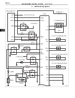
Page 163: ...AM2 AM2 AM1 AM1 ST ALT IG2 NSW STA BM BATT MREL MIL A W SPD OC1 OC1 OE1 OE1 OE2 OE2 OC2 OC2 ECM IGSW FC IG1 ST2 ST1 PNP SW Combination Meter VVT OCV Intake Side RH VVT OCV Intake Side LH VVT OCV Exhaust Side RH VVT OCV Exhaust Side LH Fuel Pump C OPN ETCS EFI No 1 EFI MAIN EFI Battery Starter FL MAIN E02 E05 E1 A137635E02 ...

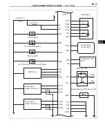
Page 164: ... ST1 IMI E04 E01 E03 ME01 CAN CAN EPA2 VCPA B VG B2 AICV ACIS PRG ACM THA E2G ETHA HT1B EX1B OX1B HT2B EX2B OX2B A B EFI No 3 EFI No 2 VSV for ACIS VSV for ACIS MAF Meter VSV for EVAP System VSV for Active Control Mount System HO2 Sensor Bank 1 Sensor 2 HO2 Sensor Bank 2 Sensor 2 Power Steering Oil Pressure SW Transponder Key ECU A137631E02 ...

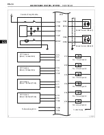
Page 165: ...jector No 5 Fuel Injector No 6 Fuel Injector To IG2 Relay ECM KNK1 MPMP EPPM KNK2 EKN2 VV1 VCV1 VV1 VV2 VCV2 VV2 EV1 VCE1 EV1 EV2 VCE2 CANH CANL EV2 EKNK 10 20 30 40 50 60 Canister Pump Module B PPMP VCPP VPMP To Main Body ECU VVT Sensor Bank 1 Intake Side VVT Sensor Bank 2 Intake Side VVT Sensor Bank 1 Exhaust Side VVT Sensor Bank 2 Exhaust Side A137632E02 ...

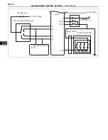
Page 166: ...n Coil No 4 Ignition Coil No 5 Ignition Coil No 6 To IG2 Relay ECM NE IGT1 IGT2 IGT3 IGT4 IGT5 IGT6 IGF1 NE TC VTA1 VTA2 GE01 HA1A HA2A A1A A1A A2A A2A ETA THW M M VCTA ETHW Throttle Body Assembly ECT Sensor Bank 1 Sensor 1 A F Sensor Bank 2 Sensor 1 A F Sensor A F A F To Battery To EFI Relay Noise Filter RH Side Noise Filter LH Side A137633E02 ...

Page 167: ...L SYSTEM SFI SYSTEM ES 11 ES GAUGE No 1 Park Neutral Position SW Transmission Control ECU ECM S P R N D SFTD SFTU CCS Transmission Control SW ECU IG No 2 Spiral Cable Cruise Control SW To IG1 Relay To IG1 Relay A137634E02 ...

Page 168: ...Side LH VVT OCV Exhaust Side RH VVT OCV Exhaust Side LH W SPD OC1 OC1 OE1 OE1 OE2 OE2 OC2 OC2 E02 E05 E1 ECM STSW STAR IGSW BATT MREL BM FC NSW STA ACCR To ECU ACC Fuse Main Body ECU ACC STR STSW STR2 ACCR IG2D IG2 IGN To IG2 Fuse ST CUT ETCS PNP SW ST AM2 ST To IGN Fuse Fuel Pump C OPN EFI No 1 EFI MAIN EFI Battery FL MAIN Starter A A137630E02 ...

Page 169: ... ST1 IMI E04 E01 E03 ME01 CAN CAN EPA2 VCPA B VG B2 AICV ACIS PRG ACM THA E2G ETHA HT1B EX1B OX1B HT2B EX2B OX2B A B EFI No 3 EFI No 2 VSV for ACIS VSV for ACIS MAF Meter VSV for EVAP System VSV for Active Control Mount System HO2 Sensor Bank 1 Sensor 2 HO2 Sensor Bank 2 Sensor 2 Power Steering Oil Pressure SW Transponder Key ECU A137631E02 ...

Page 170: ...jector No 5 Fuel Injector No 6 Fuel Injector To IG2 Relay ECM KNK1 MPMP EPPM KNK2 EKN2 VV1 VCV1 VV1 VV2 VCV2 VV2 EV1 VCE1 EV1 EV2 VCE2 CANH CANL EV2 EKNK 10 20 30 40 50 60 Canister Pump Module B PPMP VCPP VPMP To Main Body ECU VVT Sensor Bank 1 Intake Side VVT Sensor Bank 2 Intake Side VVT Sensor Bank 1 Exhaust Side VVT Sensor Bank 2 Exhaust Side A137632E02 ...

Page 171: ...n Coil No 4 Ignition Coil No 5 Ignition Coil No 6 To IG2 Relay ECM NE IGT1 IGT2 IGT3 IGT4 IGT5 IGT6 IGF1 NE TC VTA1 VTA2 GE01 HA1A HA2A A1A A1A A2A A2A ETA THW M M VCTA ETHW Throttle Body Assembly ECT Sensor Bank 1 Sensor 1 A F Sensor Bank 2 Sensor 1 A F Sensor A F A F To Battery To EFI Relay Noise Filter RH Side Noise Filter LH Side A137633E02 ...

Page 172: ...CONTROL SYSTEM SFI SYSTEM ES GAUGE No 1 Park Neutral Position SW Transmission Control ECU ECM S P R N D SFTD SFTU CCS Transmission Control SW ECU IG No 2 Spiral Cable Cruise Control SW To IG1 Relay To IG1 Relay A137634E02 ...

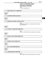
Page 173: ...the DLC3 NEXT HINT Record or print DTCs and freeze frame data if necessary NEXT NEXT NEXT NEXT HINT If the engine does not start perform steps 10 and 12 first 1 VEHICLE BROUGHT TO WORKSHOP 2 CUSTOMER PROBLEM ANALYSIS 3 CONNECT INTELLIGENT TESTER TO DLC3 4 CHECK DTC AND FREEZE FRAME DATA 5 CLEAR DTC AND FREEZE FRAME DATA 6 CONDUCT VISUAL INSPECTION 7 SET CHECK MODE DIAGNOSIS 8 CONFIRM PROBLEM SYMPT...

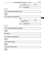
Page 174: ... B GO TO STEP 10 9 SIMULATE SYMPTOMS 10 CHECK FOR DTCS Result Proceed to Trouble code A No code B GO TO STEP 12 11 REFER TO DTC CHART GO TO STEP 14 12 CONDUCT BASIC INSPECTION Result Proceed to Malfunctioning parts not confirmed A Malfunctioning parts confirmed B GO TO STEP 17 13 REFER TO PROBLEM SYMPTOMS TABLE Result Proceed to Malfunctioning circuit confirmed A ...

Page 175: ...confirmed B GO TO STEP 17 Result Proceed to 14 CHECK ECM POWER SOURCE CIRCUIT 15 CONDUCT CIRCUIT INSPECTION Result Proceed to Malfunction not confirmed A Malfunction confirmed B GO TO STEP 18 16 CHECK FOR INTERMITTENT PROBLEMS GO TO STEP 18 17 CONDUCT PARTS INSPECTION 18 IDENTIFY PROBLEM 19 ADJUST AND OR REPAIR ...

Page 176: ...ES 20 2GR FE ENGINE CONTROL SYSTEM SFI SYSTEM ES NEXT 20 CONDUCT CONFIRMATION TEST END ...

Page 177: ...en the ECM is in check mode In check mode the ECM uses 1 trip detection logic which is more sensitive to malfunctions than normal mode default which uses 2 trip detection logic 1 Clear the DTCs 2 Switch the ECM from normal mode to check mode using an intelligent tester See page ES 49 3 Perform a simulation test See page IN 40 4 Check and wiggle the harness es connector s and terminal s See page IN...

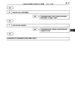
Page 178: ...efore using this check is essential when troubleshooting the engine NOTICE Carry out this check with the engine stopped and the engine switch off Result NG OK NG OK NG OK a Visually check that the air filter is not excessively contaminated with dirt or oil NG OK NG 1 CHECK BATTERY VOLTAGE Result Proceed to 11 V or more OK Below 11 V NG CHARGE OR REPLACE BATTERY 2 CHECK WHETHER ENGINE CRANKS PROCEE...

Page 179: ...NTROL SYSTEM SFI SYSTEM ES 23 ES OK NG OK NG OK 6 CHECK FUEL PRESSURE TROUBLESHOOT FUEL PRESSURE AND PROCEED TO NEXT STEP 7 CHECK FOR SPARKS TROUBLESHOOT SPARK AND PROCEED TO NEXT STEP PROCEED TO PROBLEM SYMPTOMS TABLE ...

Page 180: ...ut 1 Press the numerical button corresponding to the number that you want to input HINT Numerical characters can be selected by using the UP and DOWN buttons f Correction 1 When correcting the input character s put the cursor onto the character using the RIGHT or LEFT button 2 Select or input the correct character using the UP and DOWN buttons or the numerical buttons g Finishing Input Operation 1...

Page 181: ...e ECM is changed or the VINs do not match the VIN can be registered or overwritten in the ECM by following this procedure b Write VIN using the intelligent tester c Check the vehicle s VIN d Connect the intelligent tester to the DLC3 e Turn the ignition switch on IG f Turn the tester on Menu Screen Select VIN READ DTC P0630 Set VIN Previously Stored VIN Not Stored EXIT EXIT EXIT To Menu Screen 17 ...

Page 182: ... SFI SYSTEM ES g Enter the following menus DIAGNOSIS ENHANCED OBD ll VIN Menu Screen Select VIN WRITE VIN Previously Stored 17 digit VIN displayed To Menu Screen To Menu Screen Continue to next illustration YES YES YES NO NO A103813E01 ...

Page 183: ...2GR FE ENGINE CONTROL SYSTEM SFI SYSTEM ES 27 ES Continue to next illustration New Registration Input Error Input Instructions ENTER ENTER ENTER ENTER EXIT A103814E03 ...

Page 184: ...ES 28 2GR FE ENGINE CONTROL SYSTEM SFI SYSTEM ES Writing Successful Writing Error Communication Error To Menu Screen To Menu Screen To Menu Screen ENTER EXIT EXIT A103815E03 ...

Page 185: ...ecific procedures 1 PERFORM MONITOR DRIVE PATTERN The monitor results and test values can be checked with the OBD II scan tool or the intelligent tester The engine control module ECM monitors the emissions related components such as the thermostat catalyst converter and evaporative emissions EVAP and determines whether they are functioning normally or not When monitoring is finished the ECM stores...

Page 186: ...ent is functioning normally If not the component is malfunctioning The test value is usually significantly higher or lower than the test limit If the test value is on the borderline of the test limit the component will malfunction in the near future HINT The monitor result might be PASS on rare occasions even if the Malfunction Indicator Lamp MIL is illuminated This indicates that the system was m...

Page 187: ...k P0441 3D D7 Multiply by 0 001 kPa Test value for purge flow insufficient P0441 Monitor ID Test ID Scaling Unit Description A1 0B Multiply by 1 Time Exponential Weighted Moving Average EWMA misfire for all cylinders Misfire counts for last ten driving cycles Total A1 0C Multiply by 1 Time Misfire rate for all cylinders Misfire counts for last current driving cycles Total A2 0B Multiply by 1 Time ...

Page 188: ...ate for cylinder 6 Misfire counts for last current driving cycle Total Monitor ID Test ID Scaling Unit Description 42 91 Multiply by 0 001 Ohm Oxygen sensor heater resistance bank 1 sensor 2 46 91 Multiply by 0 004 Ohm Oxygen sensor heater resistance bank 2 sensor 2 Monitor ID Test ID Scaling Unit Description ...

Page 189: ...pection and Maintenance I M programs require a vehicle s Readiness Monitor status to show COMPL before beginning emission tests The Readiness Monitor will be reset to INCMPL incomplete if The ECM has lost battery power or broken a fuse DTCs have been cleared The conditions for running the Readiness Monitor have not been met If the Readiness Monitor status shows INCMPL follow the appropriate Readin...

Page 190: ...fuel tank is less than 90 full The altitude is less than 8 000 ft 2 450 m The vehicle is stationary The engine coolant temperature is between 4 4 C and 35 C 40 F to 95 F The intake air temperature is between 4 4 C and 35 C 40 F to 95 F Vehicle was driven in the city area or on free way for 10 minutes or more b Monitor Conditions 1 Turn the ignition switch off and wait for 6 hours HINT Do not start...

Page 191: ... fuel ratio feedback control is performed Fuel cut control is performed for 8 seconds or more for the Rear HO2 Sensor Monitor b Drive Pattern for front A F sensor and HO2 sensor 1 Connect an intelligent tester to the DLC3 2 Turn the ignition switch on IG 3 Turn the tester on 4 Clear the DTCs 5 Start the engine and warm it up until the ECT reaches 75 C 167 F or higher 6 Drive the vehicle at 38 mph ...

Page 192: ...splayed on the tester 2 If the status does not switch to COMPL complete make sure that the preconditions have been met and then perform the Drive Pattern again 5 AIR FUEL RATIO A F AND HEATED OXYGEN HO2 SENSOR HEATER MONITORS FRONT A F AND REAR HO2 SENSOR TYPE a Preconditions The monitor will not run unless The MIL is OFF b Drive Pattern 1 Connect an intelligent tester to the DLC3 2 Turn the ignit...

Page 193: ...I SYSTEM ES 37 ES c Monitor Status 1 Check the Readiness Monitor status displayed on the tester or scan tool If the status does not switch to COMPL complete make sure that the preconditions have been met and repeat the Drive Pattern ...

Page 194: ... Starter ST 143 6 STARTER relay ST 149 7 ECM power source circuit ES 432 8 ECM ES 518 No initial combustion Does not start 1 ECM power source circuit ES 432 2 Ignition system IG 3 3 Fuel pump control circuit ES 449 4 Injector FU 15 5 Crank angle sensor ES 497 6 ECM ES 518 Engine cranks normally but difficult to start 1 Electronic Throttle Control System ETCS ES 320 2 Fuel pump control circuit ES 4...

Page 195: ...e Control System ETCS ES 320 2 ECM power source circuit ES 432 3 Fuel pump control circuit ES 449 4 Spark plug IG 5 5 Ignition system IG 3 6 Injector FU 15 7 Acoustic Control Induction System ACIS ES 462 8 PCV hose EC 5 Hesitation Poor acceleration Poor driveability 1 Injector FU 15 2 Fuel pump control circuit ES 449 3 Ignition system IG 3 4 Spark plug IG 5 5 Air Intake Control System AICS ES 462 ...

Page 196: ...n signal built into pump module Ignition switch on IG 9 to 14 V MPMP A55 34 E1 C55 81 G W B Vacuum pump operation signal built into pump module Vacuum pump OFF 0 to 3 V MPMP A55 34 E1 C55 81 G W B Vacuum pump operation signal built into pump module Vacuum pump ON 9 to 14 V BM A55 3 E1 C55 81 LG W B Power source of ETCS throttle motor Always 9 to 14 V MREL A55 44 E1 C55 81 O W B EFI relay operation...

Page 197: ...rator pedal fully released 1 2 to 2 0 V EPA2 A55 60 VPA2 A55 58 O R Accelerator pedal position sensor signal for sensor malfunction detection Ignition switch on IG Accelerator pedal fully depressed 3 4 to 5 0 V PPMP C55 77 E1 C55 81 L W B Pressure sensor signal built into pump module Ignition switch on IG 3 to 3 6 V TC A55 27 E1 C55 81 P W B Terminal TC of DLC3 Ignition switch on IG 9 to 14 V VCPA...

Page 198: ...ide Ignition switch on IG Pulse generation see waveform 1 OC1 C55 58 OC1 C55 57 W B Camshaft timing Oil Control Valve OCV operation signal Intake side Ignition switch on IG Pulse generation see waveform 1 VV2 C55 67 VV2 C55 90 W B Variable Valve Timing VVT sensor signal Intake side Idling Pulse generation see waveform 5 VV1 C55 69 VV1 C55 92 L LG Variable Valve Timing VVT sensor signal Intake side...

Page 199: ... ground B W Earth ground circuit of ECM Always Below 1 V E01 C55 22 Body ground W B Earth ground circuit of ECM Always Below 1 V IGT1 C55 40 E1 C55 81 IGT2 C55 39 E1 C55 81 IGT3 C55 38 E1 C55 81 IGT4 C55 37 E1 C55 81 IGT5 C55 36 E1 C55 81 IGT6 C55 35 E1 C55 81 W W B GR W B G W B LG W B P W B G R W B Ignition coil with igniter ignition signal Idling Pulse generation see waveform 6 GE01 C55 41 E1 C5...

Page 200: ...ow 1 V HT2B C55 47 E1 C55 81 HT1B C55 48 E1 C55 81 Y W B LG W B Heated oxygen sensor heater operation signal Idling Below 3 0 V HT2B C55 47 E1 C55 81 HT1B C55 48 E1 C55 81 Y W B LG W B Heated oxygen sensor heater operation signal Ignition switch on IG 9 to 14 V E05 C55 46 E1 C55 81 W W B Earth ground circuit of ECM Always Below 1 V E04 C55 23 E1 C55 81 W W B Earth ground circuit of ECM Always Belo...

Page 201: ...ch on IG 3 3 V 1 A2A C55 119 E1 C55 81 Y W B A F sensor Ignition switch on IG 3 0 V 1 OX2B C55 87 EX2B C55 64 OX1B C55 88 EX1B C55 65 B W R W BR Heated oxygen sensor signal With engine speed at 2 500 rpm for 2 minutes after warming up Pulse generation see waveform 2 Symbols Terminal No Wiring Colors Terminal Descriptions Conditions STD Voltages 5 V DIV Ground 1 ms DIV A093229E19 ECM Terminal Names...

Page 202: ...imilar to that shown in the illustration check the waveform again after idling for 10 minutes or more Ground 1 V DIV 1 ms DIV A085286E41 ECM Terminal Names Between KNK1 and EKNK or KNK2 and EKN2 Tester Ranges 0 01 to 10 V DIV 0 01 to 10 ms DIV Conditions Engine speed is maintained at 4 000 rpm after engine is warmed up GND 5 V DIV 2 NE 1 VV1 or EV1 VV2 or EV2 GND 20 ms DIV Idling GND G035795E23 EC...

Page 203: ...tio varies depending on the throttle actuator operation k WAVEFORM 11 1 Engine speed signal HINT The wavelength becomes shorter as the engine rpm increases 2 V DIV Ground 20 ms DIV A093224E20 ECM Terminal Names Between SPD and E1 Tester Ranges 2 V DIV 20 ms DIV Conditions Driving at 12 mph 20 km h 5 V DIV Ground 1 ms DIV A093274E21 ECM Terminal Names Between M and ME01 Tester Ranges 5 V DIV 1 ms D...

Page 204: ... It minimizes a gap between technician skills and vehicle technology CAN is a network which uses a pair of data transmission lines spanning multiple computers and sensors It allows a high speed communication between the systems and simplification of the wire harness connection Since this system is equipped with the CAN communication connecting the CAN VIM VIM Vehicle Interface Module with the inte...

Page 205: ... the location of the problem connect the tester to another vehicle If communication is normal Inspect the DLC3 on the original vehicle If communication is still not possible The problem is probably in the tester itself Consult the Service Department listed in the instruction manual 6 BATTERY VOLTAGE Standard Voltage 11 to 14 V If voltage is below 11 V replace or recharge the battery before proceed...

Page 206: ...ould turn OFF when the engine is started If the MIL remains illuminated the diagnosis system has detected a malfunction or abnormality in the system HINT If the MIL is not illuminated when the engine switch is first turned on check the MIL circuit See page ES 471 ...

Page 207: ... DTC Using an intelligent tester a Connect an intelligent tester to the DLC3 b Turn the ignition switch on IG c Turn the tester on d Enter the following menu items DIAGNOSIS ENHANCED OBD II DTC INFO CURRENT CODES e Check the DTC s and freeze frame data and then write them down f Check the details of the DTC s See page ES 63 2 CLEAR DTC Using an intelligent tester a Connect an intelligent tester to...

Page 208: ...ion The data may assist in identifying of the cause of the malfunction and in judging whether it was temporary or not 2 LIST OF FREEZE FRAME DATA DTC was set 0 5 seconds 0 5 seconds Freeze frame data which can be read 0 5 seconds A103809E02 LABEL Intelligent Tester Display Measurement Item Range Diagnostic Note IGN ADVANCE Ignition advance CALC LOAD Calculate load Calculated load by ECM VEHICLE LO...

Page 209: ... LONG FT 1 Long term fuel trim Overall fuel compensation carried out in long term to compensate for a continual deviation of short term fuel trim from central valve SHORT FT 2 Short term fuel trim Short term fuel compensation used to maintain air fuel ratio at stoichiometric air fuel ratio LONG FT 2 Long term fuel trim Overall fuel compensation carried out in long term to compensate for a continua...

Page 210: ...e FUEL PMP SP CTL Fuel pump speed control status VVT CTRL B2 VVT control status bank 2 EVAP Purge VSV EVAP Purge VSV A C MAG CLUTCH A C magnetic clutch relay FUEL PUMP SPD Fuel pump speed status VVT CTRL B1 VVT control status bank 1 TC TE1 TC and TE1 terminals of DLC3 SCV DUTY RATIO SCV duty ratio VVTL AIM ANGL 1 VVT aim angle bank 1 VVT CHNG ANGL 1 VVT change angle bank 1 VVT OCV D B1 VVT OCV ope...

Page 211: ...ate Displayed only during idling MISFIRE RPM Misfire RPM MISFIRE LOAD Misfired load MISFIRE MARGIN Misfire monitoring ENG RUN TIME Accumulated engine running time TIME DTC CLEAR Cumulative time after DTC cleared DIST DTC CLEAR Accumulated distance after DTC cleared WU CYC DTC CLEAR Warm up cycle after DTC cleared LABEL Intelligent Tester Display Measurement Item Range Diagnostic Note ...

Page 212: ...URE Using an intelligent tester a Check and ensure the following conditions 1 Battery positive voltage 11 V or more 2 Throttle valve fully closed 3 Transmission in the P or N position 4 A C switch OFF b Turn the engine switch off c Connect the intelligent tester to the DLC3 d Turn the ignition switch on IG e Turn the tester on f Enter the following menus DIAGNOSIS ENHANCED OBD ll CHECK MODE g Swit...

Page 213: ...ature ECT Sensor ECM estimates ECT to be 80 C 176 F Pass condition detected P0120 P0121 P0122 P0123 P0220 P0222 P0223 P0604 P0606 P0607 P0657 P2102 P2103 P2111 P2112 P2118 P2119 and P2135 Electronic Throttle Control System ETCS ECM cuts off throttle actuator current and throttle valve returned to 6 5 throttle position by return spring ECM then adjusts engine output by controlling fuel injection in...

Page 214: ...ing CALC LOAD Load calculated by ECM Min 0 Max 100 10 to 20 Idling 10 to 20 Running without load at 2 500 rpm Load value VEHICLE LOAD Vehicle load Min 0 Max 25 700 Actual vehicle load Load percentage in terms of maximum intake air flow amount MAF Air flow rate from MAF meter Min 0 g sec Max 655 35 g sec 2 to 5 g sec Idling 8 to 19 g sec Running without load at 2 500 rpm If value is approximately 0...

Page 215: ...gine ACCEL POS 2 Absolute APP No 2 Min 0 Max 100 12 to 42 Accelerator pedal released 66 to 98 Accelerator pedal fully depressed Read value with ignition switch ON Do not start engine ACCEL POS 1 APP sensor No 1 voltage Min 0 V Max 4 98 V ETCS freeze frame data ACCEL POS 2 APP sensor No 2 voltage Min 0 V Max 4 98 V ETCS freeze frame data ACCEL POS 1 APP sensor No 1 voltage Min 0 V Max 5 V 0 5 to 1 ...

Page 216: ...ame data THROTTLE POS 1 Throttle position sensor No 1 output voltage Min 0 V Max 5 V 0 5 to 1 2 V Throttle fully closed 3 2 to 4 8 V Throttle fully open THROTTLE POS 2 Throttle position sensor No 2 output voltage Min 0 V Max 5 V 2 0 to 2 9 V Throttle fully closed 4 6 to 5 0 V Throttle fully open Read value with ignition switch ON Do not start engine THRTL COMND VAL Throttle position command value ...

Page 217: ...to 1 999 Rich AF FT B2 S1 Short term fuel trim associated with sensor 1 Min 0 Max 1 999 Value less than 1 0 000 to 0 999 Lean Stoichiometric air fuel ratio 1 Value greater than 1 1 001 to 1 999 Rich AFS B1 S1 A F sensor output voltage for bank 1 sensor 1 Min 0 V Max 7 999 V 2 8 to 3 8 V Idling Performing INJ VOL or A F CONTROL function of ACTIVE TEST enables technician to check output voltage of s...

Page 218: ... Open loop due to detected system fault CL FAULT Closed loop but A F sensor which used for fuel control malfunctioning O2FT B1 S2 Short term fuel trim associated with bank 1 sensor 2 Min 100 Max 99 2 20 to 20 Same as SHORT FT 1 O2FT B2 S2 Short term fuel trim associated with bank 2 sensor 2 Min 100 Max 99 2 20 to 20 Same as SHORT FT 2 AF FT B1 S1 Short term fuel trim associated with bank 1 sensor ...

Page 219: ... C SIGNAL A C signal ON or OFF ON A C ON PNP SW NSW PNP switch status ON or OFF ON P or N position ELECT LOAD SIG Electrical load signal ON or OFF ON Headlights or defogger turned ON STOP LIGHT SW Stop light switch ON or OFF ON Brake pedal depressed BM Whether or not electric throttle control system power input ON or OFF ON Idling BM VOLTAGE BM voltage Min 0 Max 19 922 10 to 15 V Idling ETCS servi...

Page 220: ... VVT OCV operation duty bank 1 Intake side Min 0 Max 100 0 to 100 Requested duty value for intrusive operation VVT EX HOLD B1 2 VVT exhaust hold duty ratio learning value bank 1 Exhaust side Min 0 Max 100 10 to 50 Idling Requested duty value for intrusive operation VVT EX CHG ANG1 2 VVT change angle bank 1 Exhaust side Min 0 FR Max 60 FR 0 to 5 FR Idling Displacement angle during intrusive operati...

Page 221: ...Misfire ratio of cylinder 6 Min 0 Max 255 0 This item displayed only during idling CYL ALL All cylinders misfire rate Min 0 Max 255 0 to 35 MISFIRE RPM Engine RPM for first misfire range Min 0 rpm Max 6 375 rpm 0 rpm Misfire 0 MISFIRE LOAD Engine load for first misfire range Min 0 g rev Max 3 98 g rev 0 g rev Misfire 0 MISFIRE MARGIN Misfire monitoring Min 100 Max 99 22 100 to 99 22 Misfire detect...

Page 222: ...SFIRE MON Misfire monitor NOT AVL or AVAIL O2S A FS HTR O2S A FS heater monitor NOT AVL or AVAIL O2S A FS HTR O2S A FS heater monitor COMPL or INCMPL O2S A FS MON O2S A FS monitor NOT AVL or AVAIL O2S A FS MON O2S A FS monitor COMPL or INCMPL EVAP MON EVAP monitor NOT AVL or AVAIL EVAP MON EVAP monitor COMPL or INCMPL CAT MON Catalyst monitor NOT AVL or AVAIL CAT MON Catalyst monitor COMPL or INCM...

Page 223: ...nitor COMPL or INCMPL EVAP ENA EVAP monitor UNABLE or ENABLE EVAP CMPL EVAP monitor COMPL or INCMPL HCAT ENA Heated catalyst monitor UNABLE or ENABLE HCAT CMPL Heated catalyst monitor COMPL or INCMPL CAT ENA Catalyst monitor UNABLE or ENABLE CAT CMPL Catalyst monitor COMPL or INCMPL MODEL CODE Model code information Identifying model code GSA3 ENGINE TYPE Engine type information Identifying engine...

Page 224: ...volume Lower by 12 5 or increase by 24 8 Perform test at less than 3 000 rpm A F CONTROL enables to check and to graph A F Air Fuel Ratio sensor and Heated Oxygen HO2 sensor voltage outputs To conduct test select following menu items ACTIVE TEST A F CONTROL USER DATA AFS B1S1 and O2S B1S2 and press YES and ENTER followed by F4 FUEL PMP SP CTL Fuel pump speed control ON low speed OFF high speed Tes...

Page 225: ... fuel cut ON OFF Same as above COMPRESS CHECK Check the cylinder compression pressure ON OFF Fuel injection and ignition stop in all cylinders VVT B1 Control VVT bank 1 128 to 127 This valve added to present OCV control duty 100 Maximum advance 100 Maximum retard Engine stalls or roughly idles when VVT actuator is operated by 100 Test is possible during idling VVT B2 Control VVT bank 2 Between 128...

Page 226: ...G c Turn the tester on d Enter the following menus DIAGNOSIS ENHANCED OBD II SYSTEM CHECK e Perform the SYSTEM CHECK by referring to the table below Intelligent Tester Display Test Detail Recommended Fuel Temperature Diagnostic Note EVAP SYS CHECK AUTO OPERATION Perform 4 steps in order to operate EVAP key off monitor automatically 35 C 95 F or less If no DTCs are in PENDING CODE after performing ...

Page 227: ... Camshaft Position A Timing Over Retarded Bank 1 Same as DTC P0011 Comes on DTC stored ES 84 P0013 Camshaft Position B Actuator Circuit Open Bank 1 1 Open or short in Oil Control Valve OCV for exhaust camshaft circuit 2 OCV for exhaust camshaft bank 1 3 ECM Comes on DTC stored ES 91 P0014 Camshaft Position B Timing Over Advanced or System Performance Bank 1 1 Valve timing 2 OCV for exhaust camshaf...

Page 228: ...on B Timing Over Retarded Bank 2 Same as DTC P0014 Comes on DTC stored ES 96 P0031 Oxygen A F Sensor Heater Control Circuit Low Bank 1 Sensor 1 1 Open in Air Fuel Ratio A F sensor heater circuit 2 A F sensor heater bank 1 sensor 1 3 A F sensor heater relay 4 ECM Comes on DTC stored ES 107 P0032 Oxygen A F Sensor Heater Control Circuit High Bank 1 Sensor 1 1 Short in A F sensor heater circuit 2 A F...

Page 229: ...O2 sensor heater bank 2 sensor 2 3 Engine room junction block EFI relay 4 ECM Comes on DTC stored ES 115 P0100 Mass or Volume Air Flow Circuit 1 Open or short in Mass Air Flow MAF meter circuit 2 MAF meter 3 ECM Comes on DTC stored ES 125 P0101 Mass Air Flow Circuit Range Performance Problem MAF meter Comes on DTC stored ES 133 P0102 Mass or Volume Air Flow Circuit Low Input 1 Open in MAF meter ci...

Page 230: ...red ES 145 P0120 Throttle Pedal Position Sensor Switch A Circuit Malfunction 1 Throttle Position TP sensor built into throttle body 2 ECM Comes on DTC stored ES 154 P0121 Throttle Pedal Position Sensor Switch A Circuit Range Performance Problem TP sensor built into throttle body Comes on DTC stored ES 161 P0122 Throttle Pedal Position Sensor Switch A Circuit Low Input 1 TP sensor built into thrott...

Page 231: ... Short in HO2 sensor bank 1 sensor 2 circuit 2 HO2 sensor bank 1 sensor 2 3 ECM internal circuit malfunction Comes on DTC stored ES 171 P0141 Oxygen Sensor Heater Circuit Malfunction Bank 1 Sensor 2 1 HO2 sensor 2 ECM Comes on DTC stored ES 115 P0156 Oxygen Sensor Circuit Malfunction Bank 2 Sensor 2 1 Open or short in HO2 sensor bank 2 sensor 2 circuit 2 HO2 sensor bank 2 sensor 2 3 HO2 sensor hea...

Page 232: ...A F sensor bank 1 sensor 1 circuit 8 A F sensor bank 1 sensor 1 9 A F sensor heater bank 1 sensor 1 10 A F sensor heater relay 11 A F sensor heater and A F sensor heater relay circuits 12 PCV hose connections 13 PCV valve and hose 14 ECM Comes on DTC stored ES 191 P0172 System Too Rich Bank 1 1 Injector leakage or blockage 2 MAF meter 3 ECT sensor 4 Ignition system 5 Fuel pressure 6 Gas leakage fr...

Page 233: ...system 7 Open or short in A F sensor bank 2 sensor 1 circuit 8 A F sensor bank 2 sensor 1 9 A F sensor heater bank 2 sensor 1 10 A F sensor heater relay 11 A F sensor heater and A F sensor heater relay circuits 12 ECM Comes on DTC stored ES 191 P0220 Throttle Pedal Position Sensor Switch B Circuit 1 TP sensor built into throttle body 2 ECM Comes on DTC stored ES 154 P0222 Throttle Pedal Position S...

Page 234: ...ected Same as DTC P0300 Comes on or flashes DTC stored ES 204 P0306 Cylinder 6 Misfire Detected Same as DTC P0300 Comes on or flashes DTC stored ES 204 P0327 Knock Sensor 1 Circuit Low Input Bank 1 or Single Sensor 1 Short in knock sensor 1 circuit 2 Knock sensor 1 3 ECM Comes on DTC stored ES 216 P0328 Knock Sensor 1 Circuit High Input Bank 1 or Single Sensor 1 Open in knock sensor 1 circuit 2 Kn...

Page 235: ...ank 2 Same as DTC P0340 Comes on DTC stored ES 228 P0351 Ignition Coil A Primary Secondary Circuit 1 Ignition system 2 Open or short in IGF1 or IGT circuit 1 to 6 between ignition coil and ECM 3 No 1 to No 6 ignition coils 4 ECM Comes on DTC stored ES 234 P0352 Ignition Coil B Primary Secondary Circuit Same as DTC P0351 Comes on DTC stored ES 234 P0353 Ignition Coil C Primary Secondary Circuit Sam...

Page 236: ...amshaft 3 Exhaust camshaft 4 Jumped tooth of timing chain 5 ECM Comes on DTC stored ES 243 P0392 Camshaft Position Sensor B Circuit Low Input Bank 2 1 Open or short in VVT sensor for exhaust camshaft circuit 2 VVT sensor for exhaust camshaft 3 Exhaust camshaft 4 Jumped tooth of timing chain 5 ECM Comes on DTC stored ES 243 P0393 Camshaft Position Sensor B Circuit High Input Bank 2 1 Open or short ...

Page 237: ...5 Leakage from EVAP system 6 Leakage from EVAP line EVAP VSV Intake manifold Comes on DTC stored ES 260 P0450 Evaporative Emission Control System Pressure Sensor Switch 1 Pump module including pressure sensor 2 ECM Comes on DTC stored ES 267 P0451 Evaporative Emission Control System Pressure Sensor Range Performance 1 Pump module including pressure sensor 2 Connector wire harness between pump modu...

Page 238: ...light switch 3 ECM Does not come on DTC stored ES 284 P0505 Idle Control System Malfunction 1 ETCS Electronic Throttle Control System 2 Air induction system 3 PCV hose connection 4 ECM Comes on DTC stored ES 288 P050A Cold Start Idle Air Control System Performance 1 Throttle body assembly 2 MAF meter 3 Air induction system 4 PCV hose connections 5 VVT system 6 Air cleaner filter element 7 ECM Come...

Page 239: ... in throttle actuator circuit 2 Throttle actuator 3 ECM Comes on DTC stored ES 320 P2103 Throttle Actuator Control Motor Circuit High 1 Short in throttle actuator circuit 2 Throttle actuator 3 Throttle valve 4 Throttle body assembly 5 ECM Comes on DTC stored ES 320 P2111 Throttle Actuator Control System Stuck Open 1 Throttle actuator 2 Throttle body 3 Throttle valve Comes on DTC stored ES 324 P211...

Page 240: ...ition Sensor Switch E Circuit High Input 1 Accelerator Pedal Position APP sensor 2 Open in EPA2 circuit 3 ECM Comes on DTC stored ES 334 P2135 Throttle Pedal Position Sensor Switch A B Voltage Correlation 1 Short between VTA1 and VTA2 circuits 2 TP sensor built into throttle body 3 ECM Comes on DTC stored ES 154 P2138 Throttle Pedal Position Sensor Switch D E Voltage Correlation 1 Short between VP...

Page 241: ... on DTC stored ES 364 P2239 Oxygen A F Sensor Pumping Current Circuit High Bank 1 Sensor 1 Same as DTC P2238 Comes on DTC stored ES 364 P2241 Oxygen A F Sensor Pumping Current Circuit Low Bank 2 Sensor 1 1 Open or short in A F sensor bank 2 sensor 1 circuit 2 A F sensor bank 2 sensor 1 3 A F sensor heater bank 2 sensor 1 4 A F sensor heater relay 5 A F sensor heater and relay circuits 6 ECM Comes ...

Page 242: ... Control Circuit Low 1 Pump module 2 Connector wire harness Pump module ECM 3 ECM Comes on DTC stored ES 255 P2420 EvaporativeEmission System Switching Valve Control Circuit High 1 Pump module 0 02 inch orifice vacuum pump vent valve EVAP system monitor 2 Connector wire harness Pump module ECM 3 ECM Comes on DTC stored ES 373 P2610 ECM PCM Internal Engine Off Timer Performance ECM Comes on DTC sto...

Page 243: ...r overall driving conditions The ECM detects the actual intake valve timing using signals from the camshaft and crankshaft position sensors and performs feedback control This is how the target intake valve timing is verified by the ECM DTC P0010 Camshaft Position A Actuator Circuit Bank 1 DTC P0020 Camshaft Position A Actuator Circuit Bank 2 DTC No DTC Detection Condition Trouble Area P0010 Open o...

Page 244: ...ors components Sub Frequency of operation Continuous Duration 1 second MIL operation Immediately Sequence of operation None Monitor will run whenever these DTCs are not present None All of the following conditions are met Starter OFF Engine switch ON Time after turning ignition switch off to on IG 0 5 seconds or more One of the following conditions is met Condition A B or C A All of the following ...

Page 245: ...ing freeze frame data can be helpful in determining whether the vehicle was running or stopped whether the engine was warmed up or not whether the air fuel ratio was lean or rich as well as other data recorded at the time of a malfunction See page ES 45 a Connect the intelligent tester to the DLC3 b Start the engine and turn the tester on c Warm up the engine d On the tester enter the following me...

Page 246: ... to ON CHECK FOR INTERMITTENT PROBLEMS See page ES 33 2 INSPECT CAMSHAFT TIMING OIL CONTROL VALVE ASSEMBLY A095415E03 Tester Connection Condition Specified Condition 1 2 20 C 68 F 6 9 to 7 9 Ω REPLACE CAMSHAFT TIMING OIL CONTROL VALVE ASSEMBLY See page ES 481 3 CHECK HARNESS AND CONNECTOR OCV ECM Wire Harness Side Front View OCV Connector C43 C47 C55 ECM Connector OC2 OC1 OC2 OC1 A106380E13 Tester...

Page 247: ...2GR FE ENGINE CONTROL SYSTEM SFI SYSTEM ES 91 ES OK REPLACE ECM See page ES 518 ...

Page 248: ...er DTC P0011 Camshaft Position A Timing Over Advanced or System Performance Bank 1 DTC P0012 Camshaft Position A Timing Over Retarded Bank 1 DTC P0021 Camshaft Position A Timing Over Advanced or System Performance Bank 2 DTC P0022 Camshaft Position A Timing Over Retarded Bank 2 DTC No DTC Detection Condition Trouble Area P0011 P0021 Advanced cam timing With warm engine and engine speed of between ...

Page 249: ...he engine is warm the engine coolant temperature is 75 C 167 F or more b The vehicle has been driven at more than 40 mph 64 km h for 3 minutes c The engine has idled for 3 minutes MONITOR STRATEGY TYPICAL ENABLING CONDITIONS TYPICAL MALFUNCTION THRESHOLDS Advanced camshaft timing Retard camshaft timing Related DTCs P0011 Advanced camshaft timing bank 1 P0012 Retard camshaft timing bank 1 P0021 Adv...

Page 250: ... at the time of a malfunction See page ES 45 a Connect the intelligent tester to the DLC3 b Turn the ignition switch on IG and turn the tester on c Enter the following menus DIAGNOSIS ENHANCED OBD II DTC INFO CURRENT CODES d Read the DTCs Result HINT If any DTCs other than P0011 P0012 P0021 or P0022 are output troubleshoot those DTCs first B A a Connect the intelligent tester to the DLC3 b Start t...

Page 251: ...ear the DTCs d Start the engine and warm it up e Switch the ECM from normal mode to check mode using the tester f Drive the vehicle for more than 10 minutes g Read the DTCs using the tester OK No DTC output NG OK Tester Operation Specified Condition OCV OFF Normal engine speed OCV ON Engine idles roughly or stalls soon after OCV switched from OFF to ON Go to step 4 3 CHECK WHETHER DTC OUTPUT RECUR...

Page 252: ...ears are aligned as shown in the illustration d Reinstall the cylinder head cover NG OK a Remove the OCV b Measure the resistance between the terminals of the OCV Standard resistance c Apply positive battery voltage to terminal 1 and negative battery voltage to terminal 2 Check the valve operation OK Valve moves quickly d Reinstall the OCV 4 CHECK VALVE TIMING CHECK FOR LOOSE AND JUMPED TEETH ON T...

Page 253: ... and turn the tester on c Clear the DTCs d Start the engine and warm it up e Switch the ECM from normal mode to check mode using the tester f Driver the vehicle for more than 10 minutes g Read the output DTCs using the intelligent tester OK No DTC output REPLACE CAMSHAFT TIMING OIL CONTROL VALVE ASSEMBLY See page ES 481 6 INSPECT OIL CONTROL VALVE FILTER AND PIPE RH Bank LH Bank G042497E01 CLEAN O...

Page 254: ...foreign objects in engine oil are caught in some parts of the system These codes will stay output even if the system returns to normal after a short time These foreign objects are then captured by the oil filter thus eliminating the source of the problem OK NG SYSTEM IS OK REPLACE ECM See page ES 518 ...

Page 255: ...ng conditions The ECM detects the actual exhaust valve timing using signals from the camshaft and crankshaft position sensors and performs feedback control This is how the target intake valve timing is verified by the ECM DTC P0013 Camshaft Position B Actuator Circuit Open Bank 1 DTC P0023 Camshaft Position B Actuator Circuit Open Bank 2 DTC No DTC Detection Condition Trouble Area P0013 Open or sh...

Page 256: ...DS COMPONENT OPERATING RANGE Related DTCs P0013 VVT OCV bank 1 open short P0023 VVT OCV bank 2 open short Required sensors components Main VVT OCV Variable Valve Timing oil control valve Required sensors components Sub Frequency of operation Continuous Duration 1 second MIL operation Immediate Sequence of operation None Monitor runs whenever following DTCs are not present None All of the following...

Page 257: ...troubleshooting freeze frame data can be helpful in determining whether the vehicle was running or stopped whether the engine was warmed up or not whether the air fuel ratio was lean or rich as well as other data recorded at the time of a malfunction See page ES 45 a Connect the intelligent tester to the DLC3 b Start the engine and turn the tester on c Warm up the engine d Enter the following menu...

Page 258: ...Tester Operation Specified Condition OCV OFF Normal engine speed OCV ON Engine idles roughly or stalls soon after OCV switched from OFF to ON Go to step 2 CHECK FOR INTERMITTENT PROBLEMS 2 INSPECT CAMSHAFT TIMING OIL CONTROL VALVE ASSEMBLY Valve Moves A097066E01 Tester Connection Condition Specified Condition 1 2 20 C 68 F 6 9 to 7 9 Ω Go to step 3 REPLACE CAMSHAFT TIMING OIL CONTROL VALVE ASSEMBL...

Page 259: ...V ECM Wire Harness Side Front View OCV Connector C42 C46 C55 ECM Connector OE2 OE2 OE1 OE1 A106380E14 Tester Connection Specified Condition OE1 C55 16 C42 1 Below 1 Ω OE1 C55 17 C42 2 Below 1 Ω OE2 C55 14 C46 1 Below 1 Ω OE2 C55 15 C46 2 Below 1 Ω Tester Connection Specified Condition OE1 C55 16 or C42 1 Body ground 10 kΩ or higher OE1 C55 17 or C42 2 Body ground 10 kΩ or higher OE2 C55 14 or C46 ...

Page 260: ...ted by several sensors The VVT controller regulates the exhaust camshaft angle using oil pressure through the OCV As a result the relative positions of the camshaft and crankshaft are optimized the engine torque and fuel economy improve and the exhaust emissions decrease under overall driving conditions The ECM detects the actual exhaust valve timing using signals from the camshaft and crankshaft ...

Page 261: ... CA of maximum delayed timing advanced Valve timing Oil control valve OCV for exhaust camshaft bank 1 OCV filter bank 1 Exhaust camshaft ECM P0015 P0025 Retarded cam timing With warm engine and engine speed of between 500 rpm and 4 000 rpm all conditions a b and c are met 1 trip detection logic a Difference between target and actual exhaust valve timing is more than 5 CA Crankshaft Angle for 4 5 s...

Page 262: ...cts in the OCV 5 The monitor will not run unless the following conditions are met a The engine is warm the engine coolant temperature is 75 C 167 F or more b The vehicle has been driven at more than 40 mph 64 km h for 3 minutes c The engine has idled for 3 minutes MONITOR STRATEGY TYPICAL ENABLING CONDITIONS TYPICAL MALFUNCTION THRESHOLDS Advanced camshaft timing Related DTCs P0014 Advanced camsha...

Page 263: ...ta recorded at the time of a malfunction See page ES 45 a Connect the intelligent tester to the DLC3 b Turn the ignition switch on IG and turn the tester on c Enter the following menus DIAGNOSIS ENHANCED OBD II DTC INFO CURRENT CODES d Read the DTCs Result HINT If any DTCs other than P0014 P0015 P0024 or P0025 are output troubleshoot those DTCs first B A a Connect the intelligent tester to the DLC...

Page 264: ...e page ES 45 d Start the engine and warm it up e Switch the ECM from normal mode to check mode using the tester See page ES 49 f Drive the vehicle for more than 10 minutes g Read the DTCs using the tester OK No DTC output NG OK Tester Operation Specified Condition OCV OFF Normal engine speed OCV ON Engine idles roughly or stalls soon after OCV switched from OFF to ON Go to step 4 3 CHECK WHETHER D...

Page 265: ...ligned as shown in the illustration d Reinstall the cylinder head covers NG OK a Remove the OCV b Measure the resistance between the terminals of the OCV Standard resistance c Apply positive battery voltage to terminal 1 and negative battery voltage to terminal 2 Check the valve operation OK Valve moves quickly d Reinstall the OCV 4 CHECK VALVE TIMING CHECK FOR LOOSE AND JUMPED TEETH ON TIMING CHA...

Page 266: ...onds to erase the codes b Start the engine and warm up the engine c Switch the ECM from normal mode to check mode using the intelligent tester See page ES 49 d Drive the vehicle for more than 10 minutes or more e Read the output DTCs using the intelligent tester OK No DTC output REPLACE CAMSHAFT TIMING OIL CONTROL VALVE ASSEMBLY See page ES 481 6 INSPECT OIL CONTROL VALVE FILTER AND PIPE RH Bank L...

Page 267: ...hen foreign objects in engine oil are caught in some parts of the system These codes will stay output even if the system returns to normal after a short time These foreign objects are then captured by the oil thus eliminating the source of the problem OK NG SYSTEM IS OK REPLACE ECM See page ES 518 ...

Page 268: ...CM illuminates the MIL and sets the DTC P0017 Bank 1 or P0019 Bank 2 MONITOR STRATEGY DTC P0016 Crankshaft Position Camshaft Position Corre lation Bank 1 Sensor A DTC P0017 Crankshaft Position Camshaft Position Corre lation Bank 1 Sensor B DTC P0018 Crankshaft Position Camshaft Position Corre lation Bank 2 Sensor A DTC P0019 Crankshaft Position Camshaft Position Corre lation Bank 2 Sensor B DTC No...

Page 269: ...a malfunction See page ES 45 Required sensors components Sub Camshaft position sensor Crankshaft position sensor Frequency of operation Once per drive cycle Duration Within 1 minute MIL operation 2 driving cycles Sequence of operation None Monitor runs whenever following DTCs are not present P0011 VVT system 1 advance P0012 VVT system 1 retard P0021 VVT system 2 advance P0115 P0118 ECT sensor Engi...

Page 270: ...he timing marks of the bearing cap as shown in the illustration If not turn the crankshaft 1 revolution 360 then align the marks as above OK Timing marks on camshaft timing gears are aligned as shown in the illustration d Reinstall the cylinder head covers NG OK 1 CHECK VALVE TIMING CHECK FOR LOOSE AND A JUMPED TOOTH OF TIMING CHAIN Timing Mark Timing Mark Timing Mark Timing Mark A135015E01 ADJUST...

Page 271: ...ws into the heater to heat the sensor in order to facilitate accurate oxygen concentration detection In addition the sensor and heater portions are narrower than the conventional type The heat generated by the heater is conducted to the solid electrolyte through the alumina therefore the sensor activation is accelerated A three way catalytic converter TWC is used in order to convert the carbon mon...

Page 272: ...TC No DTC Detection Condition Trouble Area P0031 P0051 Air Fuel Ratio A F sensor heater bank 1 2 sensor 1 current is less than 0 8 A 1 trip detection logic Open in A F sensor heater bank 1 2 sensor 1 circuit A F sensor heater bank 1 2 sensor 1 A F HTR relay ECM A A Element Exhaust Gas A A Section Platinum electrode Cover Air Heater Solid electrolyte Zirconia Element Rich Air Fuel Ratio Lean Ideal ...

Page 273: ... cycle approach to adjust the average current in the sensor heater element If the heater current is outside the normal range the signal transmitted by the A F sensor will be inaccurate as a result the ECM will be unable to regulate air fuel ratio properly 5 When the current in the A F sensor heater is outside the normal operating range the ECM interprets this as a malfunction in the sensor heater ...

Page 274: ...ze frame data the moment a DTC is stored When troubleshooting freeze frame data can be helpful in determining whether the vehicle was running or stopped whether the engine was warmed up or not whether the air fuel ratio was lean or rich as well as other data recorded at the time of a malfunction See page ES 45 Time after engine start 10 seconds or more Battery voltage Less than 20 V Engine Running...

Page 275: ...fuse resistance Standard resistance Below 1 Ω c Reinstall the A F fuse NG 1 INSPECT AIR FUEL RATIO SENSOR HEATER RESISTANCE Air Fuel Ratio Sensor Component Side B HA1A A1A A1A HA2A A2A A2A B C15 C35 Bank 1 Bank 2 A140627E01 Tester Connection Condition Specified Condition HA1A 1 B 2 20 C 68 F 1 8 to 3 4 Ω HA1A 1 A1A 4 10 kΩ or higher Tester Connection Condition Specified Condition HA2A 1 B 2 20 C 6...

Page 276: ...esistance Below 1 Ω c Reinstall the EFI MAIN fuse NG 4 INSPECT ENGINE ROOM JUNCTION BLOCK EFI RELAY A F RELAY Engine Room Junction Block 1G 1A 1E Engine Room Relay Block A140654E01 Tester Connection Specified Condition 1E 12 1E 6 10 kΩ or higher 1E 12 1E 6 Below 1 Ω Apply battery voltage between terminals 1E 9 and 1E 10 Tester Connection Specified Condition 1G 1 1A 4 10 kΩ or higher 1G 1 1A 4 Belo...

Page 277: ...r connector NG OK 6 CHECK HARNESS AND CONNECTOR A F SENSOR A F RELAY Bank 1 Bank 2 A1 C15 C35 Wire Harness Side A F Sensor Connector Engine Room Junction Block Engine Room Relay Block A141109E01 Tester Connection Specified Condition B C15 2 1A 4 Engine room R B Below 1 Ω B C35 2 1A 4 Engine room R B Below 1 Ω Tester Connection Specified Condition B C15 2 or 1A 4 Engine room R B Body ground 10 kΩ o...

Page 278: ...te or more g Select the following menu items DIAGNOSIS ENHANCED OBD II DTC INFO CURRENT CODES h Read the DTCs Result B A 7 CHECK HARNESS AND CONNECTOR Wire Harness Side A F Sensor Connector C15 C35 C55 ECM Connector HA2A HA1A A1A A1A A2A A2A Bank 1 Bank 2 A127715E19 Tester Connection Specified Condition HA1A C55 86 HA1A C15 1 Below 1 Ω HA2A C55 109 HA2A C35 1 Below 1 Ω Tester Connection Specified ...

Page 279: ... e less than 0 45 V Conversely when the air fuel ratio is richer than the stoichiometric air fuel level the oxygen concentration in the exhaust gas becomes lean The HO2 sensor informs the ECM that the post TWC air fuel ratio is rich high voltage i e more than 0 45 V The HO2 sensor has the property of changing its output voltage drastically when the air fuel ratio is close to the stoichiometric lev...

Page 280: ...ndition Trouble Area P0037 P0057 Heated Oxygen HO2 sensor heater current is less than 0 3 A 1 trip detection logic Open in HO2 sensor heater circuit HO2 sensor heater Engine room junction block EFI relay ECM P0038 P0058 Heated Oxygen HO2 sensor heater current is more than 2 A 1 trip detection logic Short in HO2 sensor heater circuit HO2 sensor heater Engine room junction block EFI relay ECM Atmosp...

Page 281: ...the heater current is less than 0 3 A DTC P0037 or P0057 is set Heated oxygen sensor heater performance P0141 and P0161 After the accumulated heater ON time exceeds 100 seconds the ECM calculates the heater resistance using the battery voltage and the current applied to the heater If the resistance is above the threshold value the ECM will determine that there is a malfunction in the HO2S heater a...

Page 282: ...l as other data recorded at the time of a malfunction See page ES 45 Battery voltage 10 5 to 20 V Battery voltage 10 5 V or more Engine Running Starter OFF Battery voltage 10 5 to 20 V One of the following conditions is met Condition A or B A All of the following conditions are met Conditions 1 2 3 4 and 5 1 Battery voltage 10 5 V or more 2 Fuel cut OFF 3 Time after fuel cut ON to OFF 30 seconds o...

Page 283: ...ween the terminals Standard voltage d Reconnect the HO2 sensor connector OK NG 1 INSPECT HEATED OXYGEN SENSOR HEATER RESISTANCE Component Side Heated Oxygen Sensor C52 Bank 1 C51 Bank 2 HT1B HT2B B B OX1B OX2B E2 E2 A137614E06 Tester Connection Condition Specified Condition HT1B 1 B 2 20 C 68 F 11 to 16 Ω HT1B 1 E2 4 Always 10 kΩ or higher Tester Connection Condition Specified Condition HT2B 1 B 2...

Page 284: ...he EFI relay 1 Measure the EFI relay resistance Standard resistance c Reinstall the engine room junction block NG OK 3 INSPECT FUSE EFI NO 3 Engine Room Relay Block EFI No 3 A135018E01 REPLACE EFI NO 3 FUSE 4 INSPECT ENGINE ROOM JUNCTION BLOCK Engine Room Junction Block 1E Engine Room Relay Block A140654E02 Tester Connection Specified Condition 1E 12 1E 6 10 kΩ or higher 1E 12 1E 6 Below 1 Ω Apply...

Page 285: ... 129 ES a Remove the EFI MAIN fuse from the engine room R B b Measure the EFI MAIN fuse Standard resistance Below 1 Ω c Reinstall the EFI MAIN fuse NG OK 5 INSPECT FUSE EFI MAIN EFI MAIN Engine Room Relay Block A135017E01 REPLACE EFI MAIN FUSE ...

Page 286: ...r connector NG OK 6 CHECK HARNESS AND CONNECTOR HO2 SENSOR EFI RELAY C52 Bank 1 C51 Bank 2 B B Wire Harness Side Engine Room Junction Block Heated Oxygen Sensor Connector 1E Engine Room Rlay Block A140656E01 Tester Connection Specified Condition B C52 2 1E 6 Engine room R B Below 1 Ω B C51 2 1E 6 Engine room R B Below 1 Ω Tester Connection Specified Condition B C52 2 or 1E 6 Engine room R B Body g...

Page 287: ... 7 CHECK HARNESS AND CONNECTOR HO2 SENSOR ECM Wire Harness Side Heated Oxygen Sensor Connector C52 Bank 1 C51 Bank 2 B E2 HT1B OX1B E2 OX2B B HT2B ECM Connector C55 HT1B HT2B OX2B EX1B OX1B EX2B A137615E06 Terminal Connection Specified Condition B C52 2 Body ground 9 to 14 V B C51 2 Body ground 9 to 14 V Terminal Connection Specified Condition HT1B C52 1 HT1B C55 48 Below 1 Ω OX1B C52 3 OX1B C55 8...

Page 288: ...lect the following menu items DIAGNOSIS ENHANCED OBD II DTC INFO CURRENT CODES h Read the DTCs Result B A Display DTC Output Proceed to No output A P0037 P0038 P0057 and or P0058 B REPLACE ECM See page ES 518 CHECK FOR INTERMITTENT PROBLEMS See page ES 33 ...

Page 289: ...circuit and the power transistor is controlled so that the potentials of A and B remain equal to maintain the predetermined temperature HINT When any of these DTCs are set the ECM enters fail safe mode During fail safe mode the ignition timing is calculated by the ECM according to the engine RPM and throttle valve position Fail safe mode continues until a pass condition is detected DTC P0100 Mass ...

Page 290: ...ION THRESHOLDS P0100 P0102 P0103 COMPONENT OPERATING RANGE Mass Air Flow Rate gm s Malfunctions Approximately 0 0 Open in Mass Air Flow MAF meter power source circuit Open or short in VG circuit 271 0 or more Open in EVG circuit Related DTCs P0100 Mass air flow meter range check Fluctuating P0102 Mass air flow meter range check Low voltage P0103 Mass air flow meter range check High voltage Require...

Page 291: ...s running or stopped whether the engine was warmed up or not whether the air fuel ratio was lean or rich as well as other data recorded at the time of a malfunction See page ES 45 a Connect the intelligent tester to the DLC3 b Start the engine c Turn the tester on d Enter the following menus DIAGNOSIS ENHANCED OBD II DATA LIST PRIMARY MAF e Read the values displayed on the tester 1 READ VALUE OF M...

Page 292: ...e tester probe to terminal VG and negative tester probe to terminal E2G 3 Measure the voltage between the terminals Standard voltage NG OK Mass Air Flow Rate gm s Proceed to 0 0 A 271 0 or more B Between 1 0 and 270 0 1 C Go to step 8 CHECK FOR INTERMITTENT PROBLEMS See page ES 33 2 INSPECT MASS AIR FLOW METER POWER SOURCE VOLTAGE Wire Harness Side Front View MAF Meter Connector B C2 A127724E07 Te...

Page 293: ...use resistance Standard resistance Below 1 Ω c Reinstall the EFI No 3 fuse NG OK 4 CHECK HARNESS AND CONNECTOR MASS AIR FLOW METER ECM Wire Harness Side C2 ECM Connector MAF Meter Connector E2G VG C55 E2G VG A127959E13 Tester Connection Specified Condition VG C55 72 VG C2 5 Below 1 Ω E2G C55 73 E2G C2 4 Below 1 Ω Tester Connection Specified Condition VG C55 72 or VG C2 5 Body ground 10 kΩ or highe...

Page 294: ...install the engine room junction block e Reconnect the C2 MAF meter connector NG OK 6 CHECK HARNESS AND CONNECTOR MASS AIR FLOW METER ENGINE ROOM JUNCTION BLOCK Engine Room Relay Block Engine Room Junction Block 1E C2 MAF Meter Connector Wire Harness Side A140657E01 Tester Connection Specified Condition B C2 3 1E 6 Engine room R B Below 1 Ω Tester Connection Specified Condition B C2 3 or 1E 6 Engi...

Page 295: ... connector OK NG 7 INSPECT ENGINE ROOM JUNCTION BLOCK EFI RELAY Engine Room Junction Block 1E Engine Room Relay Block A140654E02 Tester Connection Specified Condition 1E 12 1E 6 10 kΩ or higher 1E 12 1E 6 Bellow 1 Ω Apply battery voltage between terminals 1E 9 and 1E 10 REPLACE ENGINE ROOM JUNCTION BLOCK CHECK ECM POWER SOURCE CIRCUIT See page ES 432 8 CHECK HARNESS AND CONNECTOR SENSOR GROUND Wir...

Page 296: ...or e Reconnect the ECM connector NG OK 9 CHECK HARNESS AND CONNECTOR MASS AIR FLOW METER ECM Wire Harness Side C2 ECM Connector MAF Meter Connector E2G VG C55 E2G VG A127959E13 Tester Connection Specified Condition VG C55 72 VG C2 5 Below 1 Ω E2G C55 73 E2G C2 4 Below 1 Ω Tester Connection Specified Condition VG C55 72 or VG C2 5 Body ground 10 kΩ or higher E2G C55 73 or E2G C2 4 Body ground 10 kΩ...

Page 297: ...The circuit is constructed so that the platinum hot wire and the temperature sensor provide a bridge circuit and the power transistor is controlled so that the potentials of A and B remain equal to maintain the predetermined temperature HINT When any of these DTCs are set the ECM enters fail safe mode During fail safe mode the ignition timing is calculated by the ECM according to the engine RPM an...

Page 298: ...nction in the MAF meter and sets the DTC Example If the voltage is more than 2 2 V or less than 1 48 V while idling the ECM determines that there is a malfunction in the MAF meter and sets the DTC MONITOR STRATEGY TYPICAL ENABLING CONDITIONS TYPICAL MALFUNCTION THRESHOLDS WIRING DIAGRAM Refer to DTC P0100 See page ES 127 Related DTCs P0101 Mass air flow meter rationality Required Sensors Component...

Page 299: ...whether the air fuel ratio was lean or rich as well as other data recorded at the time of a malfunction See page ES 45 a Connect the intelligent tester to the DLC3 b Turn the ignition switch on IG c Turn the tester on d Enter the following menus DIAGNOSIS ENHANCED OBD II DTC INFO CURRENT CODES Result e Read the DTCs HINT If any DTCs other than P0101 are output troubleshoot those DTCs first B A 1 C...

Page 300: ...cold to improve driveability HINT When any of DTCs P0110 P0112 and P0113 are set the ECM enters fail safe mode During fail safe mode the IAT is estimated to be 20 C 68 F by the ECM Fail safe mode continues until a pass condition is detected DTC P0110 Intake Air Temperature Circuit Malfunction DTC P0112 Intake Air Temperature Circuit Low Input DTC P0113 Intake Air Temperature Circuit High Input DTC...

Page 301: ...repaired successfully a DTC is set 0 5 seconds after the engine is next started MONITOR STRATEGY TYPICAL ENABLING CONDITIONS TYPICAL MALFUNCTION THRESHOLDS P0110 P0112 P0113 COMPONENT OPERATING RANGE Temperature Displayed Malfunction 40 C 40 F Open circuit 140 C 284 F or higher Short circuit Related DTCs P0110 Intake air temperature sensor open short Fluctuating P0112 Intake air temperature sensor...

Page 302: ...h as well as other data recorded at the time of a malfunction See page ES 45 a Connect the intelligent tester to the DLC3 b Turn the ignition switch on IG c Turn the intelligent tester on d Select the following menu items DIAGNOSIS ENHANCED OBD II DTC INFO CURRENT CODES e Read the DTCs Result B C A a Connect the intelligent tester to the DLC3 b Turn the ignition switch on IG c Turn the tester on 1...

Page 303: ...Connect terminals THA and E2 of the MAF meter wire harness side connector d Connect the intelligent tester to the DLC3 e Turn the ignition switch on IG f Turn the tester on g Enter the following menus DIAGNOSIS ENHANCED OBD II DATA LIST PRIMARY INTAKE AIR h Read the value displayed on the tester Standard 140 C 284 F or higher i Reconnect the MAF meter connector OK NG Temperature Displayed Proceed ...

Page 304: ...LIST PRIMARY INTAKE AIR f Read the value displayed on the tester Standard 40 C 40 F or higher g Reconnect the MAF meter connector OK NG 4 CHECK HARNESS AND CONNECTOR MASS AIR FLOW METER ECM Wire Harness Side C2 ECM Connector MAF Meter Connector THA THA ETHA E2 C55 A127959E14 Tester Connection Specified Condition THA C55 71 THA C2 1 Below 1 Ω ETHA C55 74 E2 C2 2 Below 1 Ω Tester Connection Specifie...

Page 305: ...ndard resistance d Reconnect the MAF meter connector e Reconnect the ECM connector NG OK 6 CHECK HARNESS AND CONNECTOR MASS AIR FLOW METER ECM Wire Harness Side C2 ECM Connector MAF Meter Connector THA C55 THA A127959E15 Tester Connection Specified Condition THA C55 71 or THA C2 1 Body ground 10 kΩ or higher REPAIR OR REPLACE HARNESS OR CONNECTOR REPLACE ECM See page ES 518 ...

Page 306: ... MONITOR DESCRIPTION The ECM performs OBD II monitoring based on the values from the intake air temperature sensor If there is no change of the sensor value within the normal range the ECM will not be able to perform OBD II monitoring or will misdiagnose that there is a malfunction in the sensor The ECM detects the stuck intake air temperature sensor value by performing monitoring after the engine...

Page 307: ... Sequence of Operation None Monitor runs whenever following DTCs are not present None Time after engine start 10 seconds or more Battery voltage 10 5 V or more ECT sensor circuit OK ECT change since engine stopped Less than 180 C 356 F ECT before engine stop 70 C 158 F or more Time that MAF is low before engine stop 70 minutes Accumulated MAF amount before engine stop 3 800 g or more Key off durat...

Page 308: ...TEM ES e Read the DTCs Result HINT If any DTCs other than P0111 are output troubleshoot those DTCs first B A Display DTC Output Proceed to P0111 and other DTCs A P0111 B REPLACE MASS AIR FLOW METER See page ES 477 GO TO DTC CHART See page ES 63 ...

Page 309: ...ulate the ECT When the sensor output voltage deviates from the normal operating range the ECM interprets this as a fault in the ECT sensor and sets a DTC Example If the sensor output voltage is 40 C 40 F for 0 5 seconds or more the ECM determines that there is an open in the ECT sensor circuit and sets DTC P0118 Conversely if the voltage output is more than 140 C 284 F for 0 5 seconds or more the ...

Page 310: ...nsors Components Main Engine coolant temperature sensor Required Sensors Components Sub Frequency of Operation Continuous Duration 0 5 seconds MIL Operation Immediate Sequence of Operation None Monitor runs whenever following DTCs are not present None Engine coolant temperature sensor voltage Less than 0 14 V or more than 4 91 V Engine coolant temperature sensor voltage Less than 0 14 V Engine coo...

Page 311: ...DIAGNOSIS ENHANCED OBD II DTC INFO CURRENT CODES d Read the DTCs Result B C A a Connect the intelligent tester to the DLC3 b Turn the ignition switch on IG c Turn the tester on d Enter the following menus DIAGNOSIS ENHANCED OBD II DATA LIST PRIMARY COOLANT TEMP e Read the value displayed on the tester Standard Between 80 C and 97 C 176 F and 207 F with warm engine Result HINT If there is an open c...

Page 312: ...DLC3 e Turn the ignition switch on IG f Turn the tester on g Enter the following menus DIAGNOSIS ENHANCED OBD II DATA LIST PRIMARY COOLANT TEMP h Read the value displayed on the tester Standard 140 C 284 F or higher i Reconnect the ECT sensor connector OK NG CHECK FOR INTERMITTENT PROBLEMS 3 CHECK ENGINE COOLANT TEMPERATURE SENSOR CHECK FOR OPEN IN SENSOR ECT Sensor ECT Sensor C4 C4 ETHW ECM THW W...

Page 313: ...NOSIS ENHANCED OBD II DATA LIST PRIMARY COOLANT TEMP f Read the value displayed on the tester Standard 40 C 40 F g Reconnect the ECT sensor connector OK 4 CHECK HARNESS AND CONNECTOR ENGINE COOLANT TEMPERATURE SENSOR ECM Wire Harness Side Front View ECT Sensor Connector ECM Connector ETHW THW C4 C55 A135019E01 Tester Connection Specified Condition THW C55 79 C4 2 Below 1 Ω ETHW C55 78 C4 1 Below 1...

Page 314: ...esistance d Reconnect the ECT sensor connector e Reconnect the ECM connector NG OK 6 CHECK HARNESS AND CONNECTOR ENGINE COOLANT TEMPERATURE SENSOR ECM Wire Harness Side Front View ECT Sensor Connector ECM Connector THW C4 C55 A135019E02 Tester Connection Specified Condition THW C55 79 or C4 2 Body ground 10 kΩ or higher REPAIR OR REPLACE HARNESS OR CONNECTOR REPLACE ECM See page ES 518 ...

Page 315: ... F of the starting temperature the DTC is set 2 trip detection logic 2 Upon starting the engine the ECT is over 60 C 140 F If after driving for 250 seconds the ECM remains within 1 C 1 8 F of the starting temperature the DTC is set 6 trip detection logic MONITOR STRATEGY TYPICAL ENABLING CONDITIONS All DTC P0116 Engine Coolant Temperature Circuit Range Performance Problem DTC No DTC Detection Cond...

Page 316: ... at the time of a malfunction See page ES 45 a Connect the intelligent tester to the DLC3 b Turn the ignition switch on IG c Turn the tester on d Enter the following menus DIAGNOSIS ENHANCED II DTC INFO CURRENT CODES e Read the DTC Result Battery voltage 10 5 V or more Time after engine start 1 second or more ECT at engine start Less than 60 C 140 F IAT sensor circuit OK Soak time 5 hours Accumula...

Page 317: ...o 183 F HINT In addition to the above check confirm that the valve is completely closed when the temperature is below the standard c Reinstall the thermostat See page CO 14 NG OK P0116 and other DTCs B Display DTC output Proceed to GO TO DTC CHART See page ES 63 2 INSPECT THERMOSTAT REPLACE THERMOSTAT See page CO 13 REPLACE ENGINE COOLANT TEMPERATURE SENSOR See page ES 499 ...

Page 318: ... angle and are transmitted to the VTA terminals of the ECM As the valve closes the sensor output voltage decreases and as the valve opens the sensor output voltage increases The ECM calculates the throttle valve opening angle according to these signals and controls the throttle actuator in response to driver inputs These signals are also used in calculations such as air fuel ratio correction power...

Page 319: ...c TP sensor built into throttle body Open in VTA1 circuit Open in E2 circuit Short between VC and VTA1 circuits ECM P0220 Output voltage of VTA2 quickly fluctuates beyond lower and upper malfunction thresholds for 2 seconds 1 trip detection logic TP sensor built into throttle body ECM Throttle Valve Opening Angle degrees Throttle Position Sensor Magnet Magnet IC No 1 IC No 2 ECM 2 55 5 0 2 25 0 93...

Page 320: ...tage of VTA2 is 1 75 V or less for 2 seconds 1 trip detection logic TP sensor built into throttle body Short in VTA2 circuit Open in VC circuit ECM P0223 Output voltage of VTA2 is 4 8 V or more and VTA1 is between 0 2 V and 2 02 V for 2 seconds 1 trip detection logic TP sensor built into throttle body Open in VTA2 circuit Open in E2 circuit Short between VC and VTA2 circuits ECM P2135 Either condi...

Page 321: ...heck Low voltage 10 seconds Accelerator pedal OFF Throttle position sensor 1 range check High voltage 10 seconds Accelerator pedal OFF Throttle position sensor 2 range check Fluctuating 10 seconds Accelerator pedal OFF Throttle position sensor 2 range check Low voltage 10 seconds Accelerator pedal OFF Throttle position sensor 2 range check High voltage 10 seconds Accelerator pedal OFF Throttle pos...

Page 322: ...n be driven slowly WIRING DIAGRAM INSPECTION PROCEDURE HINT Read freeze frame data using the intelligent tester The ECM records vehicle and driving condition information as freeze frame data the moment a DTC is stored When troubleshooting freeze frame data can be helpful in determining whether the vehicle was running or stopped whether the engine was warmed up or not whether the air fuel ratio was...

Page 323: ...00 Between 4 5 V and 5 0 V 100 Between 4 5 V and 5 0 V E2 circuit open A 0 or 100 Between 2 1 V and 3 1 V Fail safe 0 or 100 Between 2 1 V and 3 1 V Fail safe VTA1 circuit open or ground short A Approx 19 Fail safe Between 0 V and 0 2 V or 4 5 V and 5 0 V Between 10 and 24 Fail safe Between 0 V and 0 2 V or 4 5 V and 5 0 V VTA2 circuit open or ground short A Between 10 and 24 Between 2 1 V and 3 1...

Page 324: ...page ES 45 d Start the engine e Allow the engine to idle for 15 seconds or more f Enter the following menus DIAGNOSIS ENHANCED OBD II DTC INFO CURRENT CODES g Read the DTCs Result B A REPAIR OR REPLACE HARNESS OR CONNECTOR 3 INSPECT ECM VC VOLTAGE 1 2 3 4 5 6 Wire Harness Side Front View Throttle Body Connector E2 VC C5 A107895E07 Tester Connection Specified Condition VC C5 5 E2 C5 3 4 5 to 5 0 V ...

Page 325: ...TA2 VTA1 is used to detect the throttle valve angle and VTA2 is used to detect malfunctions in VTA1 The sensor signal voltages vary between 0 V and 5 V in proportion to the throttle valve opening angle and are transmitted to the VTA terminals of the ECM As the valve closes the sensor output voltage decreases and as the valve opens the sensor output voltage increases The ECM calculates the throttle...

Page 326: ...No DTC Detection Condition Trouble Area P0121 Difference between VTA1 and VTA2 voltages less than 0 8 V or more than 1 6 V for 2 seconds 1 trip detection logic TP sensor built into throttle body Throttle Valve Opening Angle degrees Throttle Position Sensor Magnet Magnet IC No 1 IC No 2 ECM 2 55 5 0 2 25 0 93 0 69 VC E2 VTA1 VTA1 VTA2 VTA2 Sensor Output Voltage V Fail Safe Angle Usable Range 0 6 84...

Page 327: ...lowly Fail safe mode continues until a pass condition is detected and the engine switch is then turned off INSPECTION PROCEDURE HINT Read freeze frame data using the intelligent tester The ECM records vehicle and driving condition information as freeze frame data the moment a DTC is stored When troubleshooting freeze frame data can be helpful in determining whether the vehicle was running or stopp...

Page 328: ...I SYSTEM ES d Enter the following menus DIAGNOSIS ENHANCED II DTC INFO CURRENT CODES e Read the DTC Result B A Display DTC output Proceed to P0121 A P0121 and other DTCs B GO TO DTC CHART See page ES 63 REPLACE THROTTLE BODY See page ES 503 ...

Page 329: ...edback control The ECM interprets this as a malfunction in the sensor or cooling system and sets the DTC MONITOR STRATEGY TYPICAL ENABLING CONDITIONS DTC P0125 Insufficient Coolant Temperature for Closed Loop Fuel Control DTC No DTC Detection Condition Trouble Area P0125 Engine coolant temperature ECT does not reach closed loop enabling temperature for 20 minutes this period varies with ECT when e...

Page 330: ...witch on IG c Turn the tester on d Enter the following menus DIAGNOSIS ENHANCED OBD II DTC INFO CURRENT CODES e Read the DTCs Result HINT If any DTCs other than P0125 are output troubleshoot those DTCs first B A a Remove the thermostat See page CO 13 b Check the valve opening temperature of the thermostat Standard 80 to 84 C 176 to 183 F HINT In addition to the above check confirm that the valve i...

Page 331: ...n the cooling system that might cause the system to be too cold such as abnormal radiator fan operation or any modifications NG OK REPLACE THERMOSTAT See page CO 13 3 CHECK COOLING SYSTEM REPAIR OR REPLACE COOLING SYSTEM REPLACE ENGINE COOLANT TEMPERATURE SENSOR See page ES 499 ...

Page 332: ...ngine cooling system and sets the DTC MONITOR STRATEGY DTC P0128 Coolant Thermostat Coolant Temperature Below Thermostat Regulating Temperature DTC No DTC Detection Condition Trouble Area P0128 Conditions a b and c are met for 5 seconds 2 rip detection logic a Cold start b Engine warmed up c ECT less than 75 C 167 F Thermostat Cooling system ECT sensor ECM Related DTCs P0128 Coolant Thermostat Req...

Page 333: ...e P0022 VVT System 2 Retard P0031 P0032 P0051 P0052 A F sensor heater Sensor 1 P0100 P0103 MAF meter P0110 P0113 IAT sensor P0115 P0118 ECT sensor P0125 Insufficient ECT for Closed Loop P0171 P0172 Fuel system P0300 P0308 Misfire P0335 CKP sensor P0340 P0341 CMP sensor P0351 P0356 Ignitor P0500 VSS P2196 P2198 A F sensor rationality P2A00 P2A03 A F sensor slow response Battery voltage 11 V or more...

Page 334: ...any modifications NG OK a Remove the thermostat See page CO 13 b Check the valve opening temperature of the thermostat Standard 80 to 84 C 176 to 183 F HINT In addition to the above check confirm that the valve is completely closed when the temperature is below the standard c Reinstall the thermostat See page CO 14 NG OK Display DTC Output Proceed to P0128 A P0128 and other DTCs B GO TO DTC CHART ...

Page 335: ... is lean low voltage i e less than 0 45 V Conversely when the air fuel ratio is richer than the stoichiometric air fuel level the oxygen concentration in the exhaust gas becomes lean The HO2 sensor informs the ECM that the post TWC air fuel ratio is rich high voltage i e more than 0 45 V The HO2 sensor has the property of changing its output voltage drastically when the air fuel ratio is close to ...

Page 336: ...iod of time 2 trip detection logic a HO2 sensor voltage output less than 0 21 V b Target air fuel ratio rich High impedance Sensor impedance is 15 kΩ or more for more than 90 seconds when ECM presumes sensor to being warmed up and operating normally 2 trip detection logic Open in HO2 sensor bank 1 2 sensor 2 circuit HO2 sensor bank 1 2 sensor 2 HO2 sensor heater bank 1 2 sensor 2 Engine room junct...

Page 337: ...ot increase to more than 0 59 V during active air fuel ratio control the ECM determines that the sensor voltage output is abnormal and sets DTCs P0136 and P0156 3 Open or Short in Heated Oxygen HO2 Sensor Circuit DTCs P0137 and P0157 or P0138 and P0158 During active air fuel ratio control the ECM calculates the Oxygen Storage Capacity OSC of the Three Way Catalytic Converter TWC by forcibly regula...

Page 338: ...e ECM determines that there is a malfunction in the sensor when the measured impedance deviates from the standard range The effective resistance in an alternating current electrical circuit HINT The impedance cannot be measured using an ohmmeter HO2 SENSOR CIRCUIT LOW VOLTAGE P0137 and P0157 OPEN Active air fuel ratio control HO2 sensor voltage Target air fuel ratio Stoichiometric Air Fuel Level O...

Page 339: ...158 HO2S high voltage Extremely high Bank 2 Required Sensors Components Main HO2S Required Sensors Components Sub Crankshaft position sensor Engine coolant temperature sensor Mass air flow meter Throttle position sensor Frequency of Operation Once per driving cycle Duration 20 seconds HO2S voltage P0136 P0156 HO2S low voltage P0137 P0157 HO2S high voltage P0138 P0158 30 seconds HO2S low impedance ...

Page 340: ... start 2 seconds or more Either of the following conditions 1 or 2 is met 1 All of the following conditions a b and c are met a Commanded air fuel ratio 14 3 or less b Rear HO2S voltage 0 21 to 0 59 V c OSC Oxygen capacity of catalyst 2 g or more 2 All of the following conditions d e and f are met d Commanded air fuel ratio 14 9 or more e Rear HO2S voltage 0 21 to 0 59 V f OSC Oxygen capacity of c...

Page 341: ...OMPONENT OPERATING RANGE MONITOR RESULT Refer to CHECKING MONITOR STATUS See page ES 25 Duration that following condition is met 10 seconds or more Rear HO2S voltage 1 2 V or more Duration that following condition is met 30 seconds or more Heated oxygen sensor voltage Varies between 0 1 and 0 9 V ...

Page 342: ...d Oxygen Sensor Bank 1 Sensor 2 ECM C55 B E2 HT1B OX1B HT1B 48 C55 OX1B 88 1 1 C55 EX1B 65 C55 HT2B 47 C55 OX2B 87 C55 EX2B 64 A55 MREL 1 Shielded Battery EL MAIN EFI MAIN EFI Relay EFI No 3 44 1 2 3 4 C51 Heated Oxygen Sensor Bank 2 Sensor 2 B E2 HT2B OX2B 1 2 3 4 A133851E02 ...

Page 343: ...on 4 Clear the DTCs where set See page ES 45 5 Select the following menu items DIAGNOSIS CARB OBD II READINESS TESTS 6 Check that O2S EVAL is INCMPL incomplete 7 Start the engine and warm it up Procedure A 8 Drive the vehicle at between 40 mph and 70 mph 64 km h and 113 km h for at least 10 minutes Procedure B 9 Note the state of the Readiness Tests items Those items will change to COMPL complete ...

Page 344: ... HO2 sensors AFS B1S1 and O2S B1S2 or AFS B2S1 and O2S B2S2 displayed on the tester HINT The A F CONTROL operation lowers the fuel injection volume by 12 5 or increases the injection volume by 25 Each sensor reacts in accordance with increases in the fuel injection volume NOTICE The Air Fuel Ratio A F sensor has an output delay of a few seconds and the Heated Oxygen HO2 sensor has a maximum output...

Page 345: ...d to the B wire DTC P0136 will be set If the OX2B wire from the ECM connector is short circuited to the B wire DTC P0156 will be set a Connect the intelligent tester to the DLC3 b Turn the ignition switch on IG and turn the tester on c Enter the following menus DIAGNOSIS ENHANCED OBD II DTC INFO CURRENT CODES d Read the DTCs Result B C A a Connect the intelligent tester to the DLC3 b Turn the igni...

Page 346: ...e C55 ECM connector c Measure the resistance according to the value s in the table below Standard resistance d Reconnect the ECM connector NG OK HO2 Sensor Output Voltage Proceed to More than 1 2 V A Less than 1 0 V B Go to step 5 3 CHECK HARNESS AND CONNECTOR CHECK FOR SHORT C55 Wire Harness Side Front View ECM Connector OX2B HT2B OX1B HT1B A107892E78 Tester Connection Specified Condition HT1B C5...

Page 347: ... A 4 INSPECT HEATED OXYGEN SENSOR CHECK FOR SHORT Component Side Heated Oxygen Sensor C52 Bank 1 C51 Bank 2 HT1B HT2B B B OX1B OX2B E2 E2 A137614E04 Tester Connection Specified Condition B 2 E2 4 10 kΩ or higher B 2 OX1B 3 10 kΩ or higher Tester Connection Specified Condition B 2 E2 4 10 kΩ or higher B 2 OX2B 3 10 kΩ or higher REPLACE HEATED OXYGEN SENSOR See page EC 20 REPAIR OR REPLACE HARNESS O...

Page 348: ...ncreased HINT Quickly accelerate the engine to 4 000 rpm 3 times using the accelerator pedal Standard voltage Fluctuates between 0 4 V or less and 0 5 V or more NG OK NEXT a On the intelligent tester enter the following menus DIAGNOSIS ENHANCED OBD II DTC INFO CURRENT CODES b Read the DTCs Result B A a Replace the hated oxygen sensor See page EC 20 NEXT 7 READ VALUE OF OXYGEN SENSOR OUTPUT VOLTAGE...

Page 349: ...sensor is displayed as AFS B1S1 or AFS B2S1 and the HO2 sensor is displayed as O2S B1S2 or O2S B2S2 on the intelligent tester Result HINT A normal HO2 sensor voltage O2S B1S2 or O2S B2S2 reacts in accordance with increases and decreases in fuel injection volumes When the A F sensor voltage remains either less or more than 3 3 V despite the HO2 sensor indicating a normal reaction the A F sensor is ...

Page 350: ...ion Malfunction Injection Volume HO2 Sensor Output A F Sensor Output A087979E16 REPLACE AIR FUEL RATIO SENSOR See page EC 19 CHECK AND REPAIR EXTREMELY RICH OR LEAN ACTUAL AIR FUEL RATIO INJECTOR FUEL PRESSURE GAS LEAKAGE FROM EXHAUST SYSTEM 14 CHECK FOR EXHAUST GAS LEAKS REPAIR OR REPLACE EXHAUST GAS LEAKAGE POINT ...

Page 351: ...Standard resistance Bank 2 sensor 2 NG OK 15 INSPECT HEATED OXYGEN SENSOR HEATER RESISTANCE Component Side Heated Oxygen Sensor C52 Bank 1 C51 Bank 2 HT1B HT2B B B OX1B OX2B E2 E2 A137614E04 Tester Connection Condition Specified Condition HT1B 1 B 2 20 C 68 F 11 to 16 Ω HT1B 1 E2 4 Always 10 kΩ or higher Tester Connection Condition Specified Condition HT2B 1 B 2 20 C 68 F 11 to 16 Ω HT2B 1 E2 4 Al...

Page 352: ...ble below Standard resistance c Reinstall the engine room junction block NG OK 16 INSPECT ENGINE ROOM JUNCTION BLOCK EFI MAIN RELAY Engine Room Junction Block 1E Engine Room Relay Block A140654E02 Terminal Connection Specified Condition 1E 12 1E 6 10 kΩ or higher 1E 12 1E 6 Below 1 Ω when battery voltage applied to terminals 1E 9 and 1E 10 REPLACE ENGINE ROOM JUNCTION BLOCK ...

Page 353: ...Oxygen Sensor Connector C52 Bank 1 C51 Bank 2 B E2 HT1B OX1B E2 OX2B B HT2B ECM Connector C55 HT1B HT2B OX2B EX1B OX1B EX2B A137615E05 Terminal Connection Specified Condition B C52 2 Body ground 9 to 14 V B C51 2 Body ground 9 to 14 V Terminal Connection Specified Condition HT1B C52 1 HT1B C55 48 Below 1 Ω OX1B C52 3 OX1B C55 88 Below 1 Ω E2 C52 4 EX1B C55 65 Below 1 Ω HT2B C51 1 HT2B C55 47 Below...

Page 354: ...ference System Diagram of Bank 1 Sensor 2 From Battery EFI MAIN EFI Relay Ground Heater Sensor HO2 Sensor OX1B OX1B EX1B MREL HT1B B E2 HT1B ECM Duty Control EFI No 3 A103832E39 REPAIR OR REPLACE HARNESS OR CONNECTOR REPLACE HEATED OXYGEN SENSOR See page EC 20 ...

Page 355: ... the actual air fuel ratio is on the lean side When DTC P0172 or P0175 is set the actual air fuel ratio is on the rich side If the vehicle runs out of fuel the air fuel ratio is lean and DTC P0171 or P0174 may be set The MIL is then illuminated DTC P0171 System Too Lean Bank 1 DTC P0172 System Too Rich Bank 1 DTC P0174 System Too Lean Bank 2 DTC P0175 System Too Rich Bank 2 DTC No DTC Detection Co...

Page 356: ...ck compensation value and the average long term fuel trim learning value of the air fuel ratio If the average fuel trim learning value exceeds the malfunction thresholds the ECM interprets this as a fault in the fuel system and sets a DTC Example The average fuel trim learning value is more than 35 or less than 35 the ECM interprets this as a fuel system malfunction MONITOR STRATEGY Related DTCs P...

Page 357: ... on the tester HINT The A F CONTROL operation lowers the fuel injection volume by 12 5 or increases the injection volume by 25 Each sensor reacts in accordance with increases and decreases in the fuel injection volume Standard voltage The monitor will run whenever these DTCs are not present P0010 P0020 VVT VSV1 2 P0011 P0012 VVT System Advance Retard P0021 P0022 VVT System2 Adavance Retard P0031 P...

Page 358: ...voltage could be caused by a rich air fuel mixture Check for conditions that would cause the engine to run rich A high A F sensor voltage could be caused by a lean air fuel mixture Check for conditions that would cause the engine to run lean O2S B1S2 or O2S B2S2 HO2 25 Rich More than 0 55 O2S B1S2 or O2S B2S2 HO2 12 5 Lean Less than 0 4 Case A F Sensor Sensor 1 Output Voltage HO2 Sensor Sensor 2 O...

Page 359: ... DLC3 b Start the engine and turn the tester on c Warm up the engine at an engine speed of 2 500 rpm for approximately 90 seconds d Select the following menu items on the tester DIAGNOSIS ENHANCED OBD II ACTIVE TEST A F CONTROL e Perform the A F CONTROL operation with the engine in an idling condition press the RIGHT or LEFT button to change the fuel injection volume 1 CHECK ANY OTHER DTCS OUTPUT ...

Page 360: ...ensor alternates correctly B C Tester Display Sensor Injection Volumes Status Voltages AFS B1S1 or AFS B2S1 A F 25 Rich Less than 3 0 AFS B1S1 or AFS B2S1 A F 12 5 Lean More than 3 35 O2S B1S2 or O2S B2S2 HO2 25 Rich More than 0 55 O2S B1S2 or O2S B2S2 HO2 12 5 Lean Less than 0 4 Status AFS B1S1 or AFS B2S1 Status O2S B1S2 or O2S B2S2 A F Condition and A F Sensor Condition Misfires Suspected Troub...

Page 361: ...on c Select the following menu items DIAGNOSIS ENHANCED OBD II DATA LIST PRIMARY MAF and COOLANT TEMP d Allow the engine to idle until the COOLANT TEMP reaches 75 C 167 F or more e Read the MAF with the engine in an idling condition and at an engine speed of 2 500 rpm Standard MAF while engine is idling Between 3 2 g s and 4 7 g s shift position N A C OFF MAF at engine speed of 2 500 rpm Between 1...

Page 362: ...IST PRIMARY CYL 1 to CYL 6 NG OK a Inspect the fuel injector assembly See page FU 15 HINT If the injectors malfunction engine misfire may occur The misfire count can be read using the intelligent tester Select the following menu items DIAGNOSIS ENHANCED OBD II DATA LIST PRIMARY CYL 1 to CYL 6 NG OK 8 CHECK FOR EXHAUST GAS LEAKS REPAIR OR REPLACE EXHAUST SYSTEM 9 CHECK FOR SPARKS AND IGNITION REPAI...

Page 363: ...he A F sensor connector NG OK 11 INSPECT AIR FUEL RATIO SENSOR HEATER RESISTANCE HA1A B A1A A1A A F Sensor Bank 1 C15 C35 HA2A B A2A A2A A F Sensor Bank 2 A126269E03 Tester Connections Specified Conditions HA1A 1 B 2 1 8 to 3 4 Ω at 20 C 68 F HA1A 1 A1A 4 10 kΩ or higher Tester Connections Specified Conditions HA2A 1 B 2 1 8 to 3 4 Ω at 20 C 68 F HT2A 1 A2A 4 10 kΩ or higher REPLACE AIR FUEL RATIO...

Page 364: ...tance c Reinstall the engine room junction block NG OK 12 INSPECT ENGINE ROOM JUNCTION BLOCK A F SENSOR HEATER RELAY Engine Room Junction Block 1G 1A 1E Engine Room Relay Block A140654E01 Tester Connections Specified Conditions 1G 1 1A 4 10 kΩ or higher 1G 1 1A 4 Below 1 Ω when battery voltage applied to terminals 1E 6 and 1E 10 REPLACE ENGINE ROOM JUNCTION BLOCK ...

Page 365: ... Bank 1 C35 Bank 2 C55 ECM Connector HA1A HA2A A1A A2A A1A A2A A127715E14 Tester Connections Specified Conditions B C15 2 Body ground 9 to 14 V B C35 2 Body ground 9 to 14 V Tester Connections Specified Conditions HA1A C15 1 HA1A C55 86 Below 1 Ω A1A C15 3 A1A C55 93 Below 1 Ω A1A C15 4 A1A C55 116 Below 1 Ω HA2A C35 1 HA2A C55 109 Below 1 Ω A2A C35 3 A2A C55 120 Below 1 Ω A2A C35 4 A2A C55 119 Be...

Page 366: ...49 Procedure D e Start the engine and warm it up with all the accessories switched off Procedure E f Drive the vehicle at between 38 mph and 75 mph 60 km h and 120 km h and at an engine speed of between 1 400 rpm and 3 200 rpm for 3 to 5 minutes Procedure F Reference System Diagram of Bank 1 Sensor 1 ECM A F Sensor A F Relay From Battery From EFI Relay A F HA1A Duty Control A1A HA1A B A1A Heater S...

Page 367: ...EXT a Select the following menu items DIAGNOSIS ENHANCED OBD II DTC INFO PENDING CODES b Read the DTCs Result B A Between 1 400 rpm and 3 200 rpm Between 38 mph and 75 mph 60 km h and 120 km h Engine Speed A B C D Ignition Switch off Time Idling 2 minutes 3 to 5 minutes E F A079199E68 16 CHECK WHETHER DTC OUTPUT RECURS DTC P0171 P0172 P0174 OR P0175 Display DTC Output Proceed to No output A P0171 ...

Page 368: ...ed to measure variations in the crankshaft rotation speed Misfires are counted when the crankshaft rotation speed variations exceed predetermined thresholds If the misfire exceeds the threshold levels and may cause emission deterioration the ECM illuminates the MIL and sets a DTC DTC P0300 Random Multiple Cylinder Misfire Detected DTC P0301 Cylinder 1 Misfire Detected DTC P0302 Cylinder 2 Misfire ...

Page 369: ...l crankshaft revolutions The ECM flashes the MIL and sets a DTC when either one of the following conditions which could cause the Three Way Catalytic Converter TWC damage is detected 2 trip detection logic In every 200 crankshaft revolutions at a high engine rpm the threshold misfiring percentage is recorded once In every 200 crankshaft revolutions at a normal engine rpm the threshold misfiring pe...

Page 370: ...IL Operation 2 driving cycles Emission related misfire MIL flashes immediately Catalyst damaged misfire Sequence of Operation None Monitor runs whenever following DTCs are not present P0100 P0103 MAF meter P0110 P0113 IAT sensor P0115 P0118 ECT sensor P0120 P0223 P2135 TP sensor P0125 Insufficient ECT for Closed Loop P0327 P0333 Knock sensor P0335 CKP sensor P0340 P0341 CMP sensor P0500 VSS Batter...

Page 371: ...RAM Main Body ECU E6 No 1 Fuel Injector C7 No 2 Fuel Injector C9 No 3 Fuel Injector C8 No 4 Fuel Injector C10 No 5 Fuel Injector C36 No 6 Fuel Injector C37 Ignition SW E23 AM2 AM2 ST AM2 AM2 IG2 IG2 IG2 IG2D FL MAIN Battery 2 1 5 5 6 3 C55 C55 22 83 43 84 44 85 45 C55 C55 C55 C55 C55 ECM 10 20 30 40 50 60 E01 1 11 A134880E01 ...

Page 372: ...dition information as freeze frame data the moment a DTC is stored When troubleshooting freeze frame data can be helpful in determining whether the vehicle was running or stopped whether the engine was warmed up or not whether the air fuel ratio was lean or rich as well as other data recorded at the time of a malfunction See page ES 45 If the misfire does not recur when the vehicle is brought to t...

Page 373: ...e DTCs Result HINT If any DTCs other than P0300 P0301 P0302 P0303 P0304 P0305 and P0306 are output troubleshoot those DTCs first B A a Connect the intelligent tester to the DLC3 b Turn the ignition switch on IG and turn the tester on c Enter the following menus DIAGNOSIS ENHANCED OBD II DATA LIST MISFIRE MISFIRE RPM and MISFIRE LOAD d Read and note the MISFIRE RPM and MISFIRE LOAD engine load valu...

Page 374: ... and then check the misfire counts again h Drive the vehicle with the MISFIRE RPM and MISFIRE LOAD noted in step 2 Step D i Read the CYL 1 to 6 or DTCs displayed on the tester Step E Result B A a Remove the ignition coil and the spark plug of the misfiring cylinder b Measure the spark plug electrode gap Standard Between 1 0 mm and 1 4 mm 0 039 in and 0 055 in c Check the electrode for carbon depos...

Page 375: ... plug that functions normally b Perform a spark test CAUTION Always disconnect each injector connector NOTICE Do not crank the engine for more than 2 seconds 1 Install the spark plug to the ignition coil and connect the ignition coil connector 2 Disconnect the injector connector 3 Ground the spark plug 4 Check if sparks occur while the engine is being cranked OK Sparks jump across the electrode ga...

Page 376: ...9 to 14 V 20 C55 85 E01 C55 22 9 to 14 V 30 C55 44 E01 C55 22 9 to 14 V 40 C55 84 E01 C55 22 9 to 14 V 50 C55 43 E01 C55 22 9 to 14 V 60 C55 83 E01 C55 22 9 to 14 V Go to step 12 10 CHECK HARNESS AND CONNECTOR INJECTOR ECM Wire Harness Side Front View Injector Connector ECM Connector 40 50 30 20 60 10 C55 C7 C8 C9 C10 C36 C37 A106388E07 Tester Connection Specified Condition 10 C55 45 C7 1 Below 1 ...

Page 377: ...s poor NG OK NG OK a Check the air induction system for vacuum leakage OK No leakage from air induction system NG OK 11 CHECK FUEL INJECTOR ASSEMBLY MISFIRING CYLINDER REPLACE FUEL INJECTOR ASSEMBLY See page FU 13 12 CHECK VALVE CLEARANCE MISFIRING CYLINDER ADJUST VALVE CLEARANCE 13 CHECK AIR INDUCTION SYSTEM REPAIR OR REPLACE AIR INDUCTION SYSTEM ...

Page 378: ...shaft 1 revolution 360 and align the marks as above OK Timing marks on camshaft timing gears are aligned as shown in illustration d Reinstall the cylinder head covers NG OK a Check the fuel pressure high or low pressure Standard NG OK a Connect the intelligent tester to the DLC3 14 CHECK VALVE TIMING Timing Mark Timing Mark Timing Mark Timing Mark A135015E01 ADJUST VALVE TIMING 15 CHECK FUEL PRESS...

Page 379: ...PRIMARY MAF and COOLANT TEMP e Allow the engine to idle until the COOLANT TEMP reaches 75 C 167 F or more f Read the MAF with the engine in an idling condition and at an engine speed of 2 500 rpm Standard MAF while engine is idling Between 2 1 g sec and 3 1 g sec shift position N A C OFF MAF at an engine speed of 2 500 rpm Between 7 8 g sec and 11 4 g sec shift position N A C OFF NG OK HINT If the...

Page 380: ...on timing is delayed to its maximum retardation Fail safe mode continues until the engine switch is turned off Reference Inspection using an oscilloscope The correct waveform is as shown DTC P0327 Knock Sensor 1 Circuit Low Input Bank 1 or Single Sensor DTC P0328 Knock Sensor 1 Circuit High Input Bank 1 or Single Sensor DTC P0332 Knock Sensor 2 Circuit Low Input Bank 2 DTC P0333 Knock Sensor 2 Cir...

Page 381: ... MALFUNCTION THRESHOLDS Knock Sensor Range Check Low voltage P0327 and P0332 Knock Sensor Range Check High voltage P0328 and P0333 Equipment Settings 0 01 to 10 V DIV 0 01 to 10 ms DIV Conditions Keep engine speed at 4 000 rpm with warm engine Related DTCs P0327 Knock sensor Bank 1 open short Low voltage P0328 Knock sensor Bank 1 open short High voltage P0332 Knock sensor Bank 2 open short Low vol...

Page 382: ...ving condition information as freeze frame data the moment a DTC is stored When troubleshooting freeze frame data can be helpful in determining whether the vehicle was running or stopped whether the engine was warmed up or not whether the air fuel ratio was lean or rich as well as other data recorded at the time of a malfunction See page ES 45 ECM V2 CV1 Knock Sensor Bank 1 V1 Knock Sensor Bank 2 ...

Page 383: ...BD II DTC INFO CURRENT CODES h Read the DTCs Result i Reconnect the CV1 connector B A 1 READ OUTPUT DTC CHECK KNOCK SENSOR CIRCUIT ECM Knock Sensor 1 1 2 2 3 4 1 2 3 4 1 2 95 C55 94 C55 118 C55 117 C55 CV1 CV1 Male Female G041090E02 Male Connector Female Connector Terminal 2 Terminal 4 Terminal 1 Terminal 3 Terminal 4 Terminal 2 Terminal 3 Terminal 1 Display Proceed to DTCs same as when vehicle br...

Page 384: ...EKNK KNK1 EKN2 KNK2 A135193E01 Tester Connection Specified Condition CV1 female connector 2 KNK1 C55 95 Below 1 Ω CV1 female connector 1 EKNK C55 94 Below 1 Ω CV1 female connector 4 KNK2 C55 118 Below 1 Ω CV1 female connector 3 EKN2 C55 117 Below 1 Ω Tester Connection Specified Condition CV1 female connector 2 or KNK1 C55 95 Body ground 10 kΩ or higher CV1 female connector 1 or EKNK C55 94 Body gr...

Page 385: ...knock sensor connectors NG OK 4 INSPECT KNOCK SENSOR Wire Harness Side CV1 Male G042949E02 Tester Connection Specified Condition CV1 male connector 1 2 120 to 280 kΩ CV1 male connector 3 4 120 to 280 kΩ CHECK FOR INTERMITTENT PROBLEMS 5 CHECK HARNESS AND CONNECTOR CONNECTOR KNOCK SENSOR Wire Harness Side CV1 V1 Knock Sensor Connector Male V2 Bank 1 Bank 2 A135025E01 Tester Connection Specified Con...

Page 386: ...sensor signal and NE stands for the CKP sensor signal DTC P0335 Crankshaft Position Sensor A Circuit DTC P0339 Crankshaft Position Sensor A Circuit Inter mittent DTC No DTC Detection Condition Trouble Area P0335 No CKP sensor signal to ECM while cranking 1 trip detection logic No CKP sensor signal to ECM at engine speed of 600 rpm or more 1 trip detection logic Open or short in CKP sensor circuit ...

Page 387: ...r signal check when starter ON P0335 CKP sensor signal check when starter OFF P0335 sensor pulse check Required Sensors Components Main Crankshaft Position CKP sensor Required Sensors Components Sub Frequency of Operation Continuous Duration Within 5 seconds and 3 times MIL Operation Immediate Sequence of Operation None Monitor will run whenever these DTCs are not present Engine rpm 600 rpm or mor...

Page 388: ... 68 EV1 91 VCE2 EV2 66 EV2 89 VCV2 113 VV2 67 VV2 90 NE 110 NE 111 112 1 2 3 3 VC VVL VVL C45 VVT Sensor for Intake Camshaft bank 2 1 2 3 VC VVR VVR C41 VVT Sensor for Intake Camshaft bank 1 1 2 1 2 VC2 EX EX C44 VVT Sensor for Exhaust Camshaft bank 2 C50 Crankshaft Position Sensor 1 2 3 VC2 EX EX C40 VVT Sensor for Exhaust Camshaft bank 1 Shielded A122758E03 ...

Page 389: ... frame data using the intelligent tester The ECM records vehicle and driving condition information as freeze frame data the moment a DTC is stored When troubleshooting freeze frame data can be helpful in determining whether the vehicle was running or stopped whether the engine was warmed up or not whether the air fuel ratio was lean or rich as well as other data recorded at the time of a malfuncti...

Page 390: ...a Check the teeth of the sensor plate 2 CHECK HARNESS AND CONNECTOR CRANKSHAFT POSITION SENSOR ECM Wire Harness Side Crankshaft Position Sensor ECM Connector C50 C55 NE NE A135026E01 Tester Connection Specified Condition C50 1 NE C55 110 Below 1 Ω C50 2 NE C55 111 Below 1 Ω Tester Connection Specified Condition C50 1 or NE C55 110 Body ground 10 kΩ or higher C50 2 or NE C55 111 Body ground 10 kΩ o...

Page 391: ...2GR FE ENGINE CONTROL SYSTEM SFI SYSTEM ES 235 ES OK Sensor plate does not have any cracks or deformation NG OK REPLACE CRANKSHAFT POSITION SENSOR PLATE REPLACE ECM See page ES 518 ...

Page 392: ...haft Position Sensor A Circuit High Input Bank 1 or Single Sensor DTC P0345 Camshaft Position Sensor A Circuit Bank 2 DTC P0347 Camshaft Position Sensor A Circuit Low Input Bank 2 DTC P0348 Camshaft Position Sensor A Circuit High Input Bank 2 DTC No DTC Detection Condition Trouble Area P0340 P0345 Input voltage to ECM remains 0 3 V or less or 4 7 V or higher for more than 5 seconds when 2 or more ...

Page 393: ...or Bank 1 open short P0340 VVT position Crankshaft position misalignment Bank 1 P0342 VVT position sensor Bank 1 range check low voltage P0343 VVT position sensor Bank 1 range check high voltage P0345 VVT sensor Bank 2 open short P0345 VVT position Crankshaft position misalignment Bank 2 P0347 VVT position sensor Bank 2 range check low voltage P0348 VVT position sensor Bank 2 range check high volt...

Page 394: ...ter ON Minimum battery voltage Less than 11 V CPU initial Not initial Starter ON Battery voltage while starter is ON at least once Less than 11 V Starter OFF Engine switch ON Time after engine switch off to on 2 seconds or more Starter OFF Engine switch ON Time after engine switch off to on 2 seconds or more Battery Voltage 8 V or more Camshaft position and crankshaft position phase Misaligned Cam...

Page 395: ...he engine was warmed up or not whether the air fuel ratio was lean or rich as well as other data recorded at the time of a malfunction See page ES 45 a Disconnect the C41 or C45 VVT sensor connector b Measure the voltage according to the value s in the table below Standard voltage c Reconnect the VVT sensor connector NG OK VVT sensor voltage More than 4 7 V VVT sensor voltage 0 3 to 4 7 V 1 CHECK ...

Page 396: ...CAMSHAFT ECM Wire Harness Side VVT Sensor C41 C45 C55 Bank 1 Bank 2 ECM Connector VV2 VV1 VV1 VV2 A135027E01 Tester Connection Specified Condition VVR C41 1 VV1 C55 69 Below 1 Ω VVR C41 2 VV1 C55 92 Below 1 Ω VVL C45 1 VV2 C55 67 Below 1 Ω VVL C45 2 VV2 C55 90 Below 1 Ω Tester Connection Specified Condition VVR C41 1 or VV1 C55 69 Body ground 10 kΩ or higher VVR C41 2 or VV1 C55 92 Body ground 10 ...

Page 397: ...elligent tester on d Clear the DTCs See page ES 45 e Select the following menu items DIAGNOSIS ENHANCED OBD II DTC INFO PENDING CODES f Read the DTCs Result HINT If the engine does not start replace the ECM B A REPLACE CAMSHAFT TIMING GEAR ASSEMBLY 5 REPLACE VVT SENSOR 6 CHECK WHETHER DTC OUTPUT RECURS Display DTC Output Proceed to No output A P0340 P0342 P0343 P0345 P0347 or P0348 B REPLACE ECM S...

Page 398: ...ks of the spark plugs pass from the center electrode to the ground electrodes The ECM determines the ignition timing and transmits the ignition signals IGT to each cylinder Using the IGT signal the ECM turns the power transistor inside the igniter on and off The power transistor in turn switches on and off the current to the primary coil When the current to the primary coil is cut off a powerful v...

Page 399: ...Mass Air Flow Meter Throttle Position Sensor etc IGT1 From Battery No 1 Ignition Coil No 2 Ignition Coil No 1 Cylinder No 2 Cylinder No 3 Ignition Coil No 3 Cylinder No 4 Ignition Coil No 4 Cylinder No 5 Ignition Coil No 5 Cylinder No 6 Ignition Coil No 6 Cylinder Spark Plug Ignition Coil Igniter IGF IGT2 IGT3 IGT4 IGT5 IGT6 To Tachometer TAC A133853E01 ...

Page 400: ...n Trouble Area P0351 P0352 P0353 P0354 P0355 P0356 No IGF signal to ECM while engine is running 1 trip detection logic Ignition system Open or short in IGF1 or IGT circuit 1 to 6 between ignition coil and ECM No 1 to No 6 ignition coils ECM Item Content Terminals CH1 IGT1 IGT2 IGT3 IGT4 IGT5 IGT6 E1 CH2 IGF1 E1 Equipment Settings 2 V DIV 20 ms DIV Conditions Cranking or idling IGT and IGF Signal w...

Page 401: ...niter cylinder 4 malfunction P0355 Igniter cylinder 5 malfunction P0356 Igniter cylinder 6 malfunction Required Sensors Components Main Igniter Cylinder 1 to 6 Required Sensors Components Sub Crankshaft position sensor Frequency of Operation Continuous Duration 0 256 seconds and 4 sparks MIL Operation Immediate Sequence of Operation None Monitor runs whenever the following DTCs are not present Non...

Page 402: ... b Battery voltage 6 V or more D All of the following conditions are met a Engine speed More than 500 rpm b Battery voltage 10 V or more c Number of sparks after CPU reset 5 sparks or more Ignition signal fail count More than 2 times Ignition signal fail count No ignition confirmation signal from ignitor IGF signal Igniter transmits IGF signal when it receives IGT signal from ECM ...

Page 403: ...tion Coil B GND IGT1 IGF 1 4 3 2 B GND IGT3 IGF 1 4 3 2 B GND IGT5 IGF 1 4 3 2 B GND IGT2 IGF 1 4 3 A 2 B GND IGT4 IGF 1 4 3 2 B GND IGT6 IGF 1 4 3 2 C13 No 2 Ignition Coil C12 No 3 Ignition Coil C14 No 4 Ignition Coil C38 No 5 Ignition Coil C39 No 6 Ignition Coil IGF1 IGT2 IGT3 IGT4 IGT5 IGT6 C16 Noise Filter C49 Noise Filter A133854E01 ...

Page 404: ... ignition switch on IG c Measure the voltage according to the value s in the table below Standard voltage d Measure the resistance according to the value s in the table below Standard resistance 1 INSPECT IGNITION COIL ASSEMBLY POWER SOURCE 1 2 5 3 IG2 Relay FL MAIN Battery IG2 E6 Main Body ECU IG2D 11 A ST AM2 6 AM2 IG2 E23 Ignition SW 5 2 2 1 1 with Smart Key System 2 without Smart Key System A1...

Page 405: ...on Specified Condition IGT1 C11 3 IGT1 C55 40 Below 1 Ω IGT2 C13 3 IGT2 C55 39 Below 1 Ω IGT3 C12 3 IGT3 C55 38 Below 1 Ω IGT4 C14 3 IGT4 C55 37 Below 1 Ω IGT5 C38 3 IGT5 C55 36 Below 1 Ω IGT6 C39 3 IGT6 C55 35 Below 1 Ω Tester Connection Specified Condition IGT1 C11 3 or IGT1 C55 40 Body ground 10 kΩ or higher IGT2 C13 3 or IGT2 C55 39 Body ground 10 kΩ or higher IGT3 C12 3 or IGT3 C55 38 Body gr...

Page 406: ...onnectors c Reform a simulation test Result B A IGF C38 2 or IGF1 C55 106 Body ground 10 kΩ or higher IGF C39 2 or IGF1 C55 106 Body ground 10 kΩ or higher REPAIR OR REPLACE HARNESS OR CONNECTOR Tester Connection Specified Condition 3 PERFORM SIMULATION TEST Display DTC Output Proceed to Same DTCs that have been erased A Other DTCs B REPLACE IGNITION COIL ASSEMBLY REPLACE ECM See page ES 518 ...

Page 407: ... Camshaft Position Sensor B Circuit Low Input Bank 2 DTC P0393 Camshaft Position Sensor B Circuit High Input Bank 2 DTC No DTC Detection Condition Trouble Area P0365 P0390 Input voltage to ECM remains 0 3 V or less or 4 7 V or higher for more than 5 seconds when 2 or more seconds have elapsed after turning engine switch on IG 1 trip detection logic No VVT sensor signal to ECM during cranking 1 tri...

Page 408: ...ensor Bank 1 open short P0365 VVT position Crankshaft position misalignment Bank 1 P0367 VVT position sensor Bank 1 range check low voltage P0368 VVT position sensor Bank 1 range check high voltage P0390 VVT sensor Bank 2 open short P0390 VVT position Crankshaft position misalignment Bank 2 P0392 VVT position sensor Bank 2 range check low voltage P0393 VVT position sensor Bank 2 range check high v...

Page 409: ...e frame data can be helpful in determining whether the vehicle was running or stopped whether the engine was warmed up or not whether the air fuel ratio was lean or rich as well as other data recorded at the time of a malfunction See page ES 45 Starter OFF Engine switch ON Time after engine switch off to on 2 seconds or more Battery voltage 8 V or more Engine speed 600 rpm or more Battery voltage ...

Page 410: ...ess Side C40 Bank 1 C44 Bank 2 VVT Sensor VC2 A107149E17 Tester Connection Specified Condition VC2 C40 3 Body ground 4 5 to 5 0 V VC2 C44 3 Body ground 4 5 to 5 0 V REPAIR OR REPLACE HARNESS OR CONNECTOR 2 CHECK HARNESS AND CONNECTOR VVT SENSOR ECM Wire Harness Side VVT Sensor C40 C44 C55 Bank 1 Bank 2 ECM Connector EV2 EV1 EV1 EV2 A135027E02 Tester Connection Specified Condition EX C40 1 EV1 C55 ...

Page 411: ...e page ES 45 e Select the following menu items DIAGNOSIS ENHANCED OBD II DTC INFO PENDING CODES f Read the DTCs Result HINT If the engine does not start replace the ECM B 3 CHECK VVT SENSOR FOR EXHAUST CAMSHAFT SENSOR INSTALLATION Clearance Normal Abnormal BR03795E18 REPAIR OR REPLACE VVT SENSOR 4 CHECK EXHAUST CAMSHAFT REPLACE EXHAUST CAMSHAFT 5 REPLACE VVT SENSOR 6 CHECK WHETHER DTC OUTPUT RECUR...

Page 412: ...ES 256 2GR FE ENGINE CONTROL SYSTEM SFI SYSTEM ES A END ...

Page 413: ...he TWC If any deterioration has occurred it illuminates the MIL and sets a DTC HINT Bank 1 refers to the bank that includes cylinder No 1 Bank 2 refers to the bank that does not include cylinder No 1 Sensor 1 refers to the sensor closest to the engine assembly Sensor 2 refers to the sensor farthest away from the engine assembly MONITOR STRATEGY DTC P0420 Catalyst System Efficiency Below Threshold ...

Page 414: ...P0125 Insufficient ECT for Closed Loop P0136 P0156 O2 Sensor Sensor 2 P0171 P0172 P0174 P0175 Fuel system P0300 P0304 Misfire P0335 CKP sensor P0340 CMP sensor P0351 P0354 Igniter P0500 VSS P2196 P2198 A F Sensor rationality P2A00 P2A03 A F Sensor slow response Battery voltage 11 V or more IAT 10 C 14 F or more ECT 70 kPa 525 mmHg or more Atmospheric pressure Idle OFF Engine RPM Less than 3 200 rp...

Page 415: ...ltage HO2 Sensor Sensor 2 Output Voltage Main Suspected Trouble Area 1 Injection Volume 25 12 5 Injection Volume 25 12 5 Output Voltage More than 3 35 V Less than 3 0 V Output Voltage More than 0 55 V Less than 0 4 V 2 Injection Volume 25 12 5 Injection Volume 25 12 5 A F sensor A F sensor heater A F sensor circuit Output Voltage Almost no reaction Output Voltage More than 0 55 V Less than 0 4 V 3...

Page 416: ...Turn the ignition switch on IG and turn the tester on c Enter the following menus DIAGNOSIS ENHANCED OBD II DTC INFO CURRENT CODES d Read the DTCs Result HINT If any DTCs other than P0420 or P0430 are output troubleshoot those DTCs first B A a Connect the intelligent tester to the DLC3 b Start the engine and turn the tester on c Warm up the engine at a engine speed of 2 500 rpm for approximately 9...

Page 417: ...2S B2 S2 HO2 25 Rich More than 0 55 V O2S B1 S2 or O2S B2 S2 HO2 12 5 Lean Less than 0 4 V Status AFS B1 S1 or AFS B2 S1 Status O2S B1 S2 or O2S B2 S2 A F Condition and A F and HO2 Sensor Conditions Misfire Main Suspected Trouble Areas Proceed to Lean Rich Lean Rich Normal Three Way Catalytic Converter TWC Gas leakage from exhaust system A Lean Lean Rich A F sensor malfunction A F sensor B Rich Le...

Page 418: ... SFI SYSTEM ES C A OK No gas leakage NG OK CHECK AND REPLACE HEATED OXYGEN SENSOR AND CHECK AND REPAIR EXHAUST GAS LEAKAGE 3 CHECK FOR EXHAUST GAS LEAKAGE REPAIR OR REPLACE EXHAUST GAS LEAKAGE POINT REPLACE THREE WAY CATALYTIC CONVERTER ...

Page 419: ...i fice Clog Up DTC P043F Evaporative Emission System Reference Ori fice High Flow DTC P2401 Evaporative Emission System Leak Detection Pump Control Circuit Low DTC P2402 Evaporative Emission System Leak Detection Pump Control Circuit High DTC P2419 Evaporative Emission System Switching Valve Control Circuit Low DTCs Monitoring Items Malfunction Detection Conditions Trouble Areas Detection Timings ...

Page 420: ...used in leak check If EVAP pressure does not stabilize within 15 minutes ECM cancels EVAP system monitor 15 minutes 2 D Purge VSV monitor Purge VSV is opened and then EVAP system pressure is measured by ECM Large increase indicates normal 10 seconds E Second 0 02 inch leak pressure measurement After second 0 02 inch leak pressure measurement leak check is performed by comparing first and second 0 ...

Page 421: ... Sensors Components Pump module Frequency of Operation Once per driving cycle Duration Within 2 minutes MIL Operation 2 driving cycles Sequence of Operation None The monitor will run whenever these DTCs are not present None EVAP key off monitor is run when all of the following conditions are met Atmospheric pressure 70 to 110 kPa 525 to 825 mmHg Battery voltage 10 5 V or more Vehicle speed Below 2...

Page 422: ...measurement 1 kPa 7 5 mmHg or less 2 Reference pressure 4 85 to 1 057 kPa 36 384 to 7 929 mmHg 3 Reference pressure Saturated within 1 minute Next sequence is run if the following condition is met EVAP pressure change after vent valve is ON 0 3 kPa 2 25 mmHg or more Next sequence is run if the following condition is met Vacuum introduction time Saturated within 15 minutes Next sequence is run if t...

Page 423: ...VAP pressure just after reference pressure measurement start More than 1 kPa 7 5 mmHg Reference pressure Less than 4 85 kPa 36 384 mmHg Reference pressure 1 057 kPa 7 929 mmHg or more Reference pressure Not saturated Difference between first reference pressure and second reference pressure 0 7 kPa 5 25 mmHg or more ...

Page 424: ...ilized pressure higher than second 0 02 inch leak pressure standard x 0 2 ECM determines that EVAP VSV stuck open EVAP VSV Connector wire harness EVAP VSV ECM ECM Pump module Leakage from EVAP system While engine switch off 2 trip P0441 EVAP VSV stuck closed After EVAP leak check performed EVAP VSV turned ON open and atmospheric air introduced into EVAP system 0 02 inch leak pressure standard meas...

Page 425: ...n 70 kPa and 110 kPa 525 mmHg and 825 mmHg ECM cancels EVAP system monitor 10 seconds B First 0 02 inch leak pressure measurement In order to determine 0 02 inch leak pressure standard vacuum pump creates negative pressure vacuum through 0 02 inch orifice and then ECM checks if vacuum pump and vent valve operate normally 60 seconds C EVAP system pressure measurement Vent valve turned ON closed to ...

Page 426: ...em Pressure Measurement Operation B E 0 02 Inch Leak Pressure Measurement Operation D VSV for EVAP Monitor Canister Fuel tank Vent Valve OFF vent Pump Module Air Filter ON closed ON closed VSV for EVAP OFF 0 02 Inch Orifice Atmospheric Pressure Negative Pressure Vacuum Pump OFF ON ON ON ON OFF vent OFF OFF A106055E14 ...

Page 427: ... pressure standard x 0 2 the ECM interprets this as the EVAP VSV Vacuum Switching Valve being stuck open The ECM illuminates the MIL and sets the DTC 2 trip detection logic EVAP Pressure when VSV for EVAP Stuck Open VSV for EVAP Vent Valve Vacuum Pump 10 seconds 60 seconds 60 seconds 10 seconds Malfunction ON Open OFF Closed ON Closed ON Vent EVAP Pressure Positive Negative First 0 02 Inch Leak Pr...

Page 428: ... and the EVAP VSV vacuum Switching Valve is ON open the ECM monitors the purge flow by measuring the EVAP pressure change If negative pressure is not created the ECM begins the 2nd monitor The 2nd monitor The vent valve is turned ON closed and the EVAP pressure is then measured If the variation in the pressure is less than 0 5 kPa 3 75 mmHg the ECM interprets this as the EVAP VSV being stuck close...

Page 429: ... 5 7 or 9 5 hours EVAP pressure sensor malfunction P0450 P0451 P0452 and or P0453 Not detected EVAP VSV Not operated by scan tool Vent valve Not operated by scan tool Leak detection pump Not operated by scan tool Both of following conditions are met before key off Conditions 1 and 2 1 Duration that vehicle is being driven 5 minutes or more 2 EVAP purge operation Performed ECT 4 4 to 35 C 40 to 95 ...

Page 430: ...Monitor is complete Atmospheric pressure difference between sequence 1 and 8 0 3 kPa 2 25 mmHg or less One of the following conditions is met a EVAP VSV stuck open EVAP pressure when vacuum introduction is complete Higher than reference pressure x 0 2 b EVAP VSV stuck closed EVAP pressure change after EVAP canister purge valve is open Less than 0 3 kPa 2 25 mmHg Required Sensors Components EVAP VS...

Page 431: ...pper and lower malfunction thresholds for 0 5 seconds Pump module ECM EVAP monitoring engine switch off Engine switch on 1 trip P0451 Pressure sensor noising Sensor output voltage fluctuates frequently in a certain time period Pump module Connector wire harness Pump module ECM ECM EVAP monitoring engine switch off Engine switch running 2 trip P0451 Pressure sensor stuck Sensor output voltage does ...

Page 432: ...52 Pressure sensor voltage low If the pressure sensor output voltage is below 0 45 V the ECM interprets this as an open or short circuit malfunction in the pressure sensor or its circuit and stops the EVAP system monitor The ECM then illuminates the MIL and sets the DTC 1 trip detection logic 4 DTC P0453 Pressure sensor voltage high If the pressure sensor voltage output is 4 9 V or more the ECM in...

Page 433: ...0 kPa 825 mmHg Battery voltage 10 5 V or more Intake air temperature 4 4 to 35 C 40 to 95 F EVAP pressure sensor malfunction P0450 P0452 P0453 Not detected Either of following conditions is met 1 or 2 1 Engine Running 2 Time after key off 5 7 or 9 5 hours Atmospheric pressure Less than 70 kPa 525 mmHg or 110 kPa 825 mmHg or more Battery voltage 10 5 V or more Intake air temperature 4 4 to 35 C 40 ...

Page 434: ... ECM PRG C55 108 A55 42 C55 75 C55 76 A55 44 A55 2 C6 VSV Purge N17 Pump Module Vacuum Pump Canister Closed Valve EFI No 3 EFI No 2 EFI Relay EFI MAIN FL MAIN Battery Canister Pressure Sensor 1 9 8 6 1 4 3 2 2 B MPMP A55 34 VPMP VCPP C55 77 PPMP EPPM MREL A133856E01 ...

Page 435: ...ing the canister check the canister pump module interior and related pipes for water fuel and other liquids If liquids are present check for disconnections and or cracks in the following 1 the pipe from the air inlet port to the canister pump module 2 the canister filter and 3 the fuel tank vent hose 1 CHECK HARNESS AND CONNECTOR PUMP MODULE ECM Wire Harness Side Canister Pump Module Connector N17...

Page 436: ... Hose Air Inlet Port Inspection Area Check for disconnection and or crack A132283E04 Go to step 5 3 CHECK HARNESS AND CONNECTOR Wire Harness Side Canister Pump Module Connector SGND VOUT VCC ECM Connector VCPP PPMP EPPM N17 C55 A140651E03 Tester Connection Specified Condition N17 4 VCC C55 75 VCPP Below 1 Ω N17 3 VOUT C55 77 PPMP Below 1 Ω N17 2 SGND C55 76 EPPM Below 1 Ω Tester Connection Specifi...

Page 437: ...e ignition switch on IG do not start the engine c Turn the tester on d Wait for at least 60 seconds e Enter the following menus DIAGNOSIS ENHANCED OBD II DTC INFO PENDING CODES HINT If no pending DTCs are displayed on the tester the repair has been successfully completed NEXT 4 REPLACE ECM 5 CHECK WHETHER DTC OUTPUT RECURS AFTER REPAIR COMPLETED ...

Page 438: ...s negative pressure vacuum in EVAP system and EVAP system pressure measured 0 02 inch leak pressure standard measured at start and at end of leak check If stabilized pressure higher than second 0 02 inch leak pressure standard x 0 2 ECM determines that EVAP system has a large leak Fuel tank cap loose Leakage from EVAP line Canister Fuel tank Leakage from EVAP line EVAP VSV Canister Pump module Lea...

Page 439: ...em and EVAP system pressure then measured Write down measured value as they will be used in leak check If EVAP pressure does not stabilize within 15 minutes ECM cancels EVAP system monitor 15 minutes D EVAP VSV monitor EVAP VSV opened and then EVAP system pressure measured by ECM Large increase indicates normal 10 seconds E Second 0 02 inch leak pressure measurement After second 0 02 inch leak pre...

Page 440: ...P VSV and pump module Frequency of Operation Once per driving cycle Duration Within 15 minutes varies with amount of fuel in tank MIL Operation 2 driving cycles Sequence of Operation None EVAP key off monitor runs when all of following conditions are met Atmospheric pressure 70 to 110 kPa 525 to 825 mmHg Battery voltage 10 5 V or more Vehicle speed Below 2 5 mph 4 km h Engine switch OFF EVAP Press...

Page 441: ...onditions are met Conditions 1 2 and 3 1 EVAP pressure when 4 seconds after reference pressure measurement 1 kPa 7 5 mmHg or less 2 Reference pressure 4 85 to 1 05 kPa 36 38 to 7 87 mmHg 3 Reference pressure Saturated within 1 minute Next sequence is run if following condition is met EVAP pressure change after vent valve is ON 0 3 kPa 2 25 mmHg or more Next sequence is run if both of following con...

Page 442: ... CONTROL SYSTEM SFI SYSTEM ES P0456 EVAP small leak MONITOR RESULT Refer to CHECKING MONITOR STATUS See page ES 25 EVAP pressure when vacuum introduction is complete Between reference pressure and reference pressure x 0 2 ...

Page 443: ...nd a DTC will be set MONITOR STRATEGY TYPICAL ENABLING CONDITIONS DTC P0500 Vehicle Speed Sensor A DTC No DTC Detection Condition Trouble Area P0500 Vehicle speed signal from vehicle speed sensor is cut for 0 14 sec or more while cruise control is in operation Vehicle speed sensor Vehicle speed sensor signal circuit Combination meter ECM Skid control ECU Related DTCs P0500 Vehicle Speed Sensor Cir...

Page 444: ...whether the air fuel ratio was lean or rich as well as other data recorded at the time of a malfunction See page ES 45 a Drive the vehicle and check whether the operation of the speedometer in the combination meter is normal HINT The vehicle speed sensor is operating normally if the speedometer reading is normal Engine speed 2 000 to 5 000 rpm Engine load 30 37 or more Fuel cut high engine speed N...

Page 445: ...tester OK Vehicle speeds displayed on tester and speedometer display are equal NG OK a Disconnect the F2 combination meter connector b Turn the ignition switch on IG c Measure the voltage between the terminal of the combination meter and body ground Standard voltage d Reconnect the combination meter connector NG OK GO TO SPEEDOMETER CIRCUIT 2 READ VALUE OF INTELLIGENT TESTER VEHICLE SPEED CHECK IN...

Page 446: ...r open Standard resistance Check for short d Reconnect the combination meter connector e Reconnect the ECM connector NG 4 CHECK COMBINATION METER ASSEMBLY SPD SIGNAL WAVEFORM Wire Harness Side Combination Meter Connector F2 S 0 V 0 to 12 V Turn Wheel A132287E01 Tester Connection Specified Condition F2 12 S Body ground Voltage generated intermittently REPLACE COMBINATION METER ASSEMBLY See page ME ...

Page 447: ...2GR FE ENGINE CONTROL SYSTEM SFI SYSTEM ES 291 ES OK REPLACE ECM See page ES 518 ...

Page 448: ...ENABLING CONDITIONS DTC P0504 Brake Switch A B Correlation DTC P0724 Brake Switch B Circuit High Signal Brake Pedal Released In Transition Brake Pedal Depressed STP OFF ON ON ST1 ON ON OFF DTC No DTC Detection Condition Trouble Area P0504 Conditions a b and c continue for 0 5 seconds or more 1 trip detection logic a Ignition switch on IG b Brake pedal released c STP signal OFF when ST1 signal OFF ...

Page 449: ...n be helpful in determining whether the vehicle was running or stopped whether the engine was warmed up or not whether the air fuel ratio was lean or rich as well as other data recorded at the time of a malfunction See page ES 45 Brake switch Remain ON during GO and STOP 5 times ECM A55 35 3 4 IGN IG2 ALT 11 IG2 Relay E6 Main Body ECU IG2D STOP 2 2 1 3 5 1 ST1 A55 36 STP C55 81 E1 A19 Stop Light S...

Page 450: ... Remove the stop light switch assembly b Measure the resistance according to the value s in the table below Standard resistance c Reinstall the stop light switch assembly 1 CHECK STOP LIGHT OPERATION OF STOP LIGHT REPAIR OR REPLACE STOP LIGHT SWITCH CIRCUIT 2 READ VALUE OF INTELLIGENT TESTER STP SIGNAL AND ST1 VOLTAGE Depressed Released FI07052E06 Brake Pedal Operation Specified Condition Depresse...

Page 451: ... 4 CHECK ECM STP ST1 VOLTAGE Brake Pedal Released Brake Pedal Depressed Wire Harness Side Front View ECM Connector STP ST1 A55 A112585E08 Tester Connection Brake Pedal Operation Specified Condition STP A55 36 Body ground Depressed 9 to 14 V STP A55 36 Body ground Released 0 to 3 V ST1 A55 35 Body ground Depressed 0 to 3 V ST1 A55 35 Body ground Released 9 to 14 V REPAIR OR REPLACE HARNESS OR CONNE...

Page 452: ... ISC system is malfunctioning if the following conditions are met The learned idling air flow volume remains at the maximum or minimum 5 times or more during a driving cycle While driving at 6 mph 10 km h or more the actual engine idling speed varies from the target idling speed by between 100 rpm and 200 rpm 5 times or more during a driving cycle Example If the actual idling speed varies from the...

Page 453: ...the intelligent tester to the DLC3 b Turn the ignition switch on IG c Turn the tester on d Enter the following the menus DIAGNOSIS ENHANCED OBD II DTC INFO CURRENT CODES e Read the DTCs Result Related DTCs P0505 ISC function Required Sensors Components Main ETCS Required Sensors Components Sub Crankshaft position sensor Engine coolant temperature sensor and Vehicle speed sensor Frequency of Operat...

Page 454: ...ottle valve and the housing If necessary clean the throttle body And check that the throttle valve moves smoothly OK Throttle valve is not contamainated with foreign objects and moves smoothly NG OK P0505 and other DTCs B Display DTC output Proceed to GO TO DTC CHART See page ES 63 2 CHECK PCV HOSE HOSE CONNECTIONS REPAIR OR REPLACE PCV HOSE 3 CHECK AIR INDUCTION SYSTEM REPAIR OR REPLACE AIR INDUC...

Page 455: ...ction Conditions Trouble Areas P050A Accumulated intake air amount during 10 seconds of idling after cold start less than threshold 2 trip detection logic Throttle body assembly Mass air flow meter Air induction system PCV hose connections VVT system Air cleaner filter element ECM P050B Ignition timing retard value insufficient for 5 seconds or more during 10 seconds of P050A monitoring at cold st...

Page 456: ... inspection or repairs the ISC learning values are cleared The ISC learning must be performed by warming up the engine and idling for 5 minutes with the ECT at 75 C 167 F or more because DTCs cannot be detected with the ISC learning values cleared MONITOR STRATEGY TYPICAL ENABLING CONDITIONS P050A P050B Related DTCs P050A Idle speed control problem at cold P050B Idle ignition timing problem at col...

Page 457: ...T CODES e Read the DTCs Result HINT If any DTCs other than P050A and P050B are output troubleshoot those DTCs first B A HINT Calculate the total fuel trim values to check the characteristic deviation of the mass air flow meter a Connect the intelligent tester to the DLC3 b Turn the ignition switch on IG c Turn the tester on d Select the following menu items DIAGNOSIS ENHANCED OBD II DATA LIST PRIM...

Page 458: ...amaged NG OK a Check the air induction system for vacuum leakage OK No leakage from air induction system NG OK a Visually check that the air cleaner filter element is not excessively contaminated with dirt or oil OK Air cleaner filter element is not excessively contaminated with dirt or oil Go to step 12 3 PERFORM ACTIVE TEST USING INTELLIGENT TESTER OPERATE OCV Tester Operations Specified Conditi...

Page 459: ...es smoothly NG OK NEXT NEXT Go to step 11 7 REPLACE MASS AIR FLOW METER Go to step 15 8 CHECK AND REPAIR VVT SYSTEM Go to step 15 9 REPAIR OR REPLACE PCV HOSE Go to step 15 10 REPAIR OR REPLACE AIR INDUCTION SYSTEM Go to step 15 11 REPLACE AIR CLEANER FILTER ELEMENT SUB ASSEMBLY Go to step 15 12 CHECK THROTTLE VALVE Go to step 14 13 REPLACE ECM Go to step 15 14 REPAIR OR REPLACE THROTTLE BODY ASSE...

Page 460: ... data a Connect the intelligent tester to the DLC3 b Turn the ignition switch on IG c Turn the tester on d Clear the DTCs See page ES 45 e Switch the ECM from normal mode to check mode using the tester See page ES 49 f Start the engine to idle for a minute OK Stable fast idling g Read the DTCs OK No DTC output NEXT 15 CHECK WHETHER DTC OUTPUT RECURS DTC P050A AND OR P050B END ...

Page 461: ...NT If DTC P0560 is set the ECM does not store other DTCs MONITOR STRATEGY TYPICAL ENABLING CONDITIONS TYPICAL MALFUNCTION THRESHOLDS DTC P0560 System Voltage DTC No DTC Detection Condition Trouble Area P0560 Open in ECM back up power source circuit 1 trip detection logic Open in back up power source circuit ECM Related DTCs P0560 ECM system voltage Required Sensors Components Main ECM Required Sen...

Page 462: ...nformation as freeze frame data the moment a DTC is stored When troubleshooting freeze frame data can be helpful in determining whether the vehicle was running or stopped whether the engine was warmed up or not whether the air fuel ratio was lean or rich as well as other data recorded at the time of a malfunction See page ES 45 ECM EFI No 1 BATT A55 20 E1 C55 81 FL MAIN Battery A122745E02 ...

Page 463: ...ES a Remove the EFI No 1 fuse from the engine room R B b Measure the EFI No 1 fuse resistance Standard resistance Below 1 Ω c Reinstall the EFI No 1 fuse NG OK 1 INSPECT FUSE EFI NO 1 Engine Room Relay Block EFI No 1 A135030E01 REPLACE EFI NO 1 FUSE ...

Page 464: ...connect the positive battery terminal 5 Disconnect the negative battery terminal 6 Reinstall the EFI No 1 fuse NG OK a Check that the battery is not depleted OK Battery is not depleted NG OK 2 CHECK HARNESS AND CONNECTOR Engine Room Relay Block A55 BATT EFI No 1 Fuse ECM Connector A132292E02 Tester Connection Specified Condition Engine room R B EFI No 1 fuse terminal 2 BATT A55 20 Below 1 Ω Tester...

Page 465: ...intelligent tester on d Clear the DTCs See page ES 45 e Turn the intelligent tester off f Start the engine and turn the intelligent tester on g Select the following menu items DIAGNOSIS ENHANCED OBD II DTC INFO CURRENT CODES h Read the DTCs Result B A 4 CHECK BATTERY TERMINAL REPAIR OR REPLACE BATTERY TERMINAL 5 CHECK WHETHER DTC OUTPUT RECURS Display DTC Output Proceed to P0560 A No output B CHEC...

Page 466: ...RATEGY TYPICAL ENABLING CONDITIONS TYPICAL MALFUNCTION THRESHOLDS ECM RAM errors P0604 ECM CPU range check P0606 DTC P0604 Internal Control Module Random Access Mem ory RAM Error DTC P0606 ECM PCM Processor DTC P0607 Control Module Performance DTC P0657 Actuator Supply Voltage Circuit Open DTC No DTC Detection Condition Trouble Area P0604 P0606 P0607 P0657 ECM internal error 1 trip detection logic...

Page 467: ...her data recorded at the time of a malfunction See page ES 45 a Connect the intelligent tester to the DLC3 b Turn the ignition switch on IG c Turn the tester on d Enter the following menus DIAGNOSIS ENHANCED II DTC INFO CURRENT CODES e Read the DTCs Result B A Either A or B is met A Following conditions are met CPU reset 1 time or more Learned TP learned APP 0 4 V or more Throttle actuator OFF B C...

Page 468: ...d c are met positive B battery voltage 10 5 V or more applied to ECM for 20 seconds 1 trip detection logic a Vehicle speed more than 12 4 mph 20 km h b Engine speed more than 1 000 rpm c STA signal ON Park Neutral Position PNP switch Starter relay circuit Cranking holding function circuit With smart key system Ignition switch Without smart key system ECM Related DTCs P0617 Starter signal Required ...

Page 469: ...Body ECU With Smart Key System A55 STSW 14 A55 ACCR STSW ACCR IG2D STR2 STR 13 E9 E6 4 E9 6 E7 8 E6 11 3 C55 STAR 63 C55 NSW 62 STA A55 48 FL MAIN ST AM2 C1 Park Neutral Position SW IG2 IGN ST CUT Starter ST IG2 D1 1 2 1 3 5 2 1 5 3 5 3 9 4 B L P N 1 2 C3 1 Battery A133858E02 ...

Page 470: ...n troubleshooting freeze frame data can be helpful in determining whether the vehicle was running or stopped whether the engine was warmed up or not whether the air fuel ratio was lean or rich as well as other data recorded at the time of a malfunction See page ES 45 a Connect the intelligent tester to the DLC3 b Turn the ignition switch on IG and turn the tester on 1 READ VALUE OF INTELLIGENT TES...

Page 471: ...w Standard resistance 3 Reconnect the PNP switch connector Result B C A Engine Switch Condition ON IG ENGINE START STARTER SIG OFF ON REPLACE ECM See page ES 518 2 INSPECT PARK NEUTRAL POSITION SWITCH ASSEMBLY Component Side Park Neutral Position Switch C1 A107908E03 Gear Selector Lever Position Tester Connection Specified Condition P 4 5 Below 1 Ω N 4 5 Below 1 Ω Result Proceed to OK without smar...

Page 472: ...menus DIAGNOSIS ENHANCED OBD II DATA LIST ALL STARTER SIG d Check the value displayed on the tester when the ignition switch is turned on IG and the ignition is started OK NG OK 3 INSPECT IGNITION SWITCH ASSEMBLY Component Side Ignition Switch E23 A135034E01 Switch Condition Tester Connection Specified Condition LOCK 3 4 5 7 10 kΩ or higher START 3 4 5 7 Below 1 Ω REPAIR OR REPLACE IGNITION SWITCH...

Page 473: ...us DIAGNOSIS ENHANCED OBD II DTC INFO CURRENT CODES d Read the DTCs Result If any DTCs other than P0630 are output troubleshoot those DTCs first DTC P0630 VIN not Programmed or Mismatch ECM PCM DTC No DTC Detection Condition Trouble Area P0630 VIN not stored in ECM Input VIN in ECM not accurate ECM Related DTCs P0630 VIN not programmed Required Sensors Components Main ECM Required Sensors Componen...

Page 474: ... the VIN must be input to the ECM using the intelligent tester However all DTCs are cleared automatically by the tester when inputting the VIN If DTCs other than P0630 are set check them first B A NEXT GO TO DTC CHART See page ES 518 2 INPUT VIN WITH INTELLIGENT TESTER END ...

Page 475: ...on PRNDL Input DTC No DTC Detection Condition Trouble Area P0705 A Any 2 or more signals of the following are ON simultaneously 2 trip detection logic P input signal is ON N input signal is ON R input signal is ON D input signal is ON B Any 2 or more signals of the following are ON simultaneously 2 trip detection logic NSW input signal is ON R input signal is ON D input signal is ON C Any of follo...

Page 476: ...al input at the same time 2 or more Park position switch ON Neutral position switch ON R range position switch ON D range position switch ON Number of the following signal input at the same time 2 or more Park neutral position switch ON R range switch ON D range switch ON M switch ON Park position switch OFF Neutral position switch OFF Park neutral position switch OFF R range switch OFF D range sw...

Page 477: ... values Do not depend solely on these reference values when deciding whether a part is faulty or not 1 READ DATA LIST a Turn the ignition switch off b Connect the intelligent tester together with the CAN VIM controller area network vehicle interface module to the DLC3 c Turn the ignition switch on IG d Turn on the tester e Select the item DIAGNOSIS ENHANCED OBD II DATA LIST C1 Park Neutral Positio...

Page 478: ... P or N OFF When the shift lever position displayed on the intelligent tester differs from the actual position adjustment of the PNP switch or the shift cable may be incorrect REVERSE PNP SW Status ON or OFF Shift lever position is R ON Except R OFF DRIVE PNP SW Status ON or OFF Shift lever position is D and S ON Except D or S OFF 1 CHECK HARNESS AND CONNECTOR BATTERY PARK NEUTRAL POSITION SWITCH ...

Page 479: ...PARK NEUTRAL POSITION SWITCH BODY GROUND 1 2 3 4 9 8 7 6 5 C1 Wire Harness Side Park Neutral Position SW C117645E10 Tester Connection Specified Condition L C1 9 Body ground Below 1 Ω REPAIR OR REPLACE HARNESS OR CONNECTOR 4 INSPECT PARK NEUTRAL POSITION SWITCH ASSEMBLY C1 Component Side Park Neutral Position SW C110340E45 Shift Position Tester Connection Specified Condition P 1 3 and 4 9 Below 1 Ω...

Page 480: ...htly due to lighting up of the back up light NG OK 5 CHECK HARNESS AND CONNECTOR P D N R S ECM Connector ECM Connector Wire Harness Side C55 A55 C136857E05 Shift Position Tester Connection Specified Condition P C55 24 P Body ground 10 to 14 V Except P Below 1 V N C55 27 N Body ground 10 to 14 V Except N Below 1 V R C55 25 R Body ground 10 to 14 V Except R Below 1 V D and S C55 26 D Body ground 10 ...

Page 481: ... to the value s in the table below when the shift lever is moved to each position Standard resistance NG OK 6 CHECK HARNESS AND CONNECTOR Transmission Control Switch E31 Wire Harness Side C110345E20 Tester Connection Specified Condition 3 Body ground 10 to 14 V REPAIR OR REPLACE HARNESS OR CONNECTOR 7 INSPECT TRANSMISSION CONTROL SWITCH E31 Component Side Transmission Control Switch C136860E03 Shi...

Page 482: ...tage NG OK 8 CHECK HARNESS AND CONNECTOR P D N R S ECM Connector ECM Connector Wire Harness Side C55 A55 C136857E05 Shift Position Tester Connection Specified Condition P C55 24 P Body ground 10 to 14 V Except P Below 1 V N C55 27 N Body ground 10 to 14 V Except N Below 1 V R C55 25 R Body ground 10 to 14 V Except R Below 1 V D and S C55 26 D Body ground 10 to 14 V Except D and S Below 1 V S and A...

Page 483: ...r open Standard resistance Check for short NG OK 9 CHECK HARNESS AND CONNECTOR PARK NEUTRAL POSITION SWITCH ECM 1 2 3 4 5 6 7 8 9 NSW Park Neutral Position SW C55 ECM Connector C1 Wire Harness Side C136861E06 Tester Connection Specified Condition B C1 4 NSW C55 62 Below 1 Ω Tester Connection Specified Condition B C1 4 or NSW C55 62 Body ground 10 kΩ or higher REPAIR OR REPLACE HARNESS OR CONNECTOR...

Page 484: ...his as the current being outside the standard range and illuminates the MIL and sets a DTC If the malfunction is not repaired successfully a DTC is set when the engine is quickly revved up to a high rpm several times after the engine has idled for 5 seconds after engine start MONITOR STRATEGY TYPICAL ENABLING CONDITIONS All DTC P2102 Throttle Actuator Control Motor Circuit Low DTC P2103 Throttle A...

Page 485: ...pening angle to allow the vehicle to continue running at a minimal speed If the accelerator pedal is depressed gently the vehicle can be driven slowly Fail safe mode continues until a pass condition is detected and the engine switch is then turned off Throttle motor ON Duty cycle ratio to open throttle actuator 80 or more Throttle actuator power supply 8 V or more Current motor current Motor curre...

Page 486: ...tor current THROTTLE MOT and the throttle actuator duty ratio THROTTLE OPN THROTTLE CLS can be read using the intelligent tester However the ECM shuts off the throttle actuator current when the ETCS malfunctions a Disconnect the C5 throttle body connector b Measure the resistance according to the value s in the table below Standard resistance c Reconnect the throttle body connector NG OK 1 INSPECT...

Page 487: ...lve opens and closes smoothly NG OK 2 CHECK HARNESS AND CONNECTOR THROTTLE CONTROL MOTOR ECM 1 2 3 4 5 6 Wire Harness Side Front View Throttle Body Connector C5 ECM Connector C55 M M M M A115662E07 Tester Connection Specified Condition M C5 2 M C55 19 Below 1 Ω M C5 1 M C55 18 Below 1 Ω Tester Connection Specified Condition M C5 2 or M C55 19 Body ground 10 kΩ or higher M C5 1 or M C55 18 Body gro...

Page 488: ...fully open and close the throttle valve after the engine is next started MONITOR STRATEGY TYPICAL ENABLING CONDITIONS All P2111 Throttle actuator stuck open P2112 Throttle actuator stuck closed DTC P2111 Throttle Actuator Control System Stuck Open DTC P2112 Throttle Actuator Control System Stuck Closed DTC No DTC Detection Condition Trouble Area P2111 ECM signals throttle actuator to close but stu...

Page 489: ...using the intelligent tester The ECM records vehicle and driving condition information as freeze frame data the moment a DTC is stored When troubleshooting freeze frame data can be helpful in determining whether the vehicle was running or stopped whether the engine was warmed up or not whether the air fuel ratio was lean or rich as well as other data recorded at the time of a malfunction See page ...

Page 490: ...urn the tester on d Clear the DTCs See page ES 45 e Start the engine and fully depress and release the accelerator pedal quickly to fully open and close the throttle valve f Enter the following menus DIAGNOSIS ENHANCED OBD II DTC INFO CURRENT CODES g Read the DTCs Result B A GO TO DTC CHART See page ES 63 2 INSPECT THROTTLE BODY VISUALLY CHECK THROTTLE VALVE REPLACE THROTTLE BODY ASSEMBLY See page...

Page 491: ...s the battery supply voltage applied to the throttle actuator When the power supply voltage BM drops below 4 V for 0 8 seconds or more the ECM interprets this as an open in the power supply circuit BM The ECM illuminates the MIL and sets the DTC If the malfunction is not repaired successfully the DTC is set 5 seconds after the engine is next started MONITOR STRATEGY DTC P2118 Throttle Actuator Con...

Page 492: ...e fuel injection intermittent fuel cut and ignition timing in accordance with the accelerator pedal opening angle to allow the vehicle to continue running at a minimal speed If the accelerator pedal is depressed firmly and gently the vehicle can be driven slowly Fail safe mode continues until a pass condition is detected and the ignition switch is then turned off WIRING DIAGRAM MIL Operation Immed...

Page 493: ...well as other data recorded at the time of a malfunction See page ES 45 a Remove the ETCS fuse from the engine room R B b Measure the resistance of the ETCS fuse Standard resistance Below 1 Ω c Reinstall the ETCS fuse NG OK a Disconnect the A55 ECM connector b Measure the voltage according to the value s in the table below Standard voltage c Reconnect the ECM connector OK NG 1 CHECK FUSE ETCS FUSE...

Page 494: ...lue s in the table below Standard resistance Check for open Standard resistance Check for short 5 Reinstall the ETCS fuse 6 Reconnect the positive battery terminal 7 Reconnect the negative battery terminal NG OK 3 CHECK HARNESS AND CONNECTOR ECM ETCS FUSE ETCS FUSE BATTERY ECM Connector A55 BM ETCS Engine Room Junction Block A140650E01 Tester Connection Specified Condition Engine room R B ETCS fus...

Page 495: ...he throttle valve after the engine speed reaches 5 000 rpm by fully depressing the accelerator pedal fully open the throttle valve MONITOR STRATEGY TYPICAL ENABLING CONDITIONS TYPICAL MALFUNCTION THRESHOLDS DTC P2119 Throttle Actuator Control Throttle Body Range Performance DTC No DTC Detection Condition Trouble Area P2119 Throttle valve opening angle continues to vary greatly from target opening ...

Page 496: ...ving condition information as freeze frame data the moment a DTC is stored When troubleshooting freeze frame data can be helpful in determining whether the vehicle was running or stopped whether the engine was warmed up or not whether the air fuel ratio was lean or rich as well as other data recorded at the time of a malfunction See page ES 45 a Connect the intelligent tester to the DLC3 b Turn th...

Page 497: ... menus DIAGNOSIS ENHANCED OBD II DTC INFO CURRENT CODES i Read the DTCs HINT The output voltage of the throttle position sensor can be checked during procedure B using the intelligent tester Variations in the output voltage indicate that the throttle actuator is in operation To check the output voltage using the intelligent tester enter the following menus DIAGNOSIS ENHANCED OBD II DATA LIST PRIMA...

Page 498: ... the actual accelerator pedal opening angle throttle valve opening angle and is used for engine control A signal from VPA2 conveys the status of the VPA circuit and is used to check the APP sensor itself The ECM monitors the actual accelerator pedal opening angle throttle valve opening angle through the signals from VPA and VPA2 and controls the throttle actuator according to these signals DTC P21...

Page 499: ...yond upper and lower malfunction thresholds for 0 5 seconds or more 1 trip detection logic APP sensor ECM P2127 VPA2 is 1 2 V or less for 0 5 seconds or more when accelerator pedal is fully released 1 trip detection logic APP sensor Open in VCP2 circuit Open or ground short in VPA2 circuit ECM P2128 Conditions a and b continue for 2 0 seconds or more 1 trip detection logic a VPA2 is 4 8 V or more ...

Page 500: ...eased ACCEL POS 2 When AP Released ACCEL POS 1 When AP Depressed ACCEL POS 2 When AP Depressed VCP circuit open 0 to 0 4 V 0 to 1 2 V 0 to 0 4 V 0 to 1 2 V Open or ground short in VPA circuit 0 to 0 4 V 1 2 to 2 0 V 0 to 0 4 V 3 4 to 5 0 V Open or ground short in VPA2 circuit 0 5 to 1 1 V 0 to 0 2 V 2 6 to 4 5 V 0 to 0 2 V EPA circuit open 4 5 to 5 0 V 4 5 to 5 0 V 4 5 to 5 0 V 4 5 to 5 0 V Normal...

Page 501: ...etected and the engine switch is then turned off Monitor runs whenever following DTCs are not present None One of the following conditions is met VPA voltage when VPA2 is 0 04 V or more 0 4 V or less VPA voltage 4 8 V or more VPA voltage when VPA2 is 0 04 V or more 0 4 V or less VPA voltage 4 8 V or more One of the following conditions is met VPA2 voltage when VPA 0 04 V or more 1 2 V or less VPA2...

Page 502: ...ese DTCs relate to the Accelerator Pedal Position APP sensor a Connect the intelligent tester to the DLC3 b Turn the ignition switch on IG and turn the tester on c Enter the following menus DIAGNOSIS ENHANCED OBD II DATA LIST ALL ACCEL POS 1 and ACCEL POS 2 d Read the value displayed on the tester Standard voltage OK NG 1 READ VALUE OF INTELLIGENT TESTER ACCEL POS 1 AND ACCEL POS 2 Accelerator Ped...

Page 503: ...PA2 VCPA VCPA A17 A55 A115665E06 Tester Connection Specified Condition VPA A17 6 VPA A55 55 Below 1 Ω EPA A17 5 EPA A55 59 Below 1 Ω VCPA A17 4 VCPA A55 57 Below 1 Ω VPA2 A17 3 VPA2 A55 56 Below 1 Ω EPA2 A17 2 EPA2 A55 60 Below 1 Ω VCP2 A17 1 VCP2 A55 58 Below 1 Ω Tester Connection Specified Condition VPA A17 6 or VPA A55 55 body ground 10 kΩ or higher EPA A17 5 or EPA A55 59 body ground 10 kΩ or ...

Page 504: ...e engine e Allow the engine to idle for 15 seconds f Enter the following menus DIAGNOSIS ENHANCED OBD II DTC INFO CURRENT CODES g Read the DTCs Result B A 4 REPLACE ACCELERATOR PEDAL ROD ASSEMBLY 5 CHECK WHETHER DTC OUTPUT RECURS ACCELERATOR PEDAL POSITION SENSOR DTCS Display DTC Output Proceed to P2120 P2122 P2123 P2125 P2127 P2128 and or P2138 A No output B SYSTEM IS OK REPLACE ECM See page ES 5...

Page 505: ...angle and is used for engine control A signal from VPA2 conveys the status of the VPA circuit and is used to check the APP sensor itself The ECM monitors the actual accelerator pedal opening angle throttle valve opening angle through the signals from VPA and VPA2 and controls the throttle actuator according to these signals DTC P2121 Throttle Pedal Position Sensor Switch D Circuit Range Performanc...

Page 506: ...e ECM regards the opening angle of the accelerator pedal as being fully closed In this case the throttle valve remains closed as if the engine is idling If a pass condition is detected and then the ignition switch is turned off the fail safe operation stops and the system returns to a normal condition WIRING DIAGRAM Refer to DTC P2120 See page ES 338 INSPECTION PROCEDURE HINT Read freeze frame dat...

Page 507: ...POS 1 AP 1 ACCEL POS 2 AP 2 Released 0 5 to 1 1 V 1 2 to 2 0 V Depressed 2 6 to 4 5 V 3 4 to 4 7 V Go to step 3 2 CHECK HARNESS AND CONNECTOR ACCELERATOR PEDAL POSITION SENSOR ECM 1 2 3 4 5 6 Wire Harness Side Front View APP Sensor Connector ECM Connector VCP2 VCP2 VPA VPA EPA2 EPA2 EPA EPA VPA2 VPA2 VCPA VCPA A17 A55 A115665E06 Tester Connection Specified Condition VPA A17 6 VPA A55 55 Below 1 Ω ...

Page 508: ...See page ES 45 d Start the engine e Allow the engine to idle for 15 seconds f Enter the following menus DIAGNOSIS ENHANCED OBD II DTC INFO CURRENT CODES g Read the DTCs Result B A 3 REPLACE ACCELERATOR PEDAL ROD ASSEMBLY 4 CHECK WHETHER DTC OUTPUT RECURS ACCELERATOR PEDAL POSITION SENSOR DTCS Display DTC Output Proceed to P2121 A No output B END REPLACE ECM See page ES 518 ...

Page 509: ...s low a current flows into the heater to heat the sensor in order to facilitate accurate oxygen concentration detection In addition the sensor and heater portions are narrower than the conventional type The heat generated by the heater is conducted to the solid electrolyte through the alumina therefore the sensor activation is accelerated A three way catalytic converter TWC is used in order to con...

Page 510: ...xygen HO2 sensor voltage is 0 15 V or more Open or short in A F sensor bank 1 2 sensor 1 circuit A F sensor bank 1 2 sensor 1 A F sensor bank 1 2 sensor 1 heater A F sensor heater relay A F sensor heater and relay circuits Air induction system Injector ECM P2195 P2197 While fuel cut operation is performed during vehicle deceleration air fuel ratio A F sensor current is 3 6 mA or more for 3 seconds...

Page 511: ...el mixture causes a high A F sensor current Therefore the sensor output becomes low during acceleration and it becomes high during deceleration with the throttle valve fully closed The ECM monitors the A F sensor current during fuel cut and detects any abnormal current values 4 If the A F sensor output is 3 6 mA or more for more than 3 seconds of cumulative time the ECM interprets this as a malfun...

Page 512: ...0172 Fuel system P0300 P0308 Misfire P0335 CKP sensor P0340 P0341 CMP sensor P0500 VSS Time while all of following conditions are met 2 seconds or more Rear HO2 sensor voltage 0 15 V or more Time after engine start 30 seconds or more A F sensor status Activated Fuel system status Closed loop Engine Running The monitor will run whether these DTCs are not present P0031 P0032 P0051 P0052 A F sensor h...

Page 513: ...s whenever following DTCs are not present P0031 P0032 P0051 P0052 A F sensor heater Sensor 1 P0037 P0038 P0057 P0058 HO2 sensor heater Sensor 2 P0100 P0103 MAF meter P0110 P0113 IAT sensor P0115 P0118 ECT sensor P0120 P0223 P2135 TP sensor P0125 Insufficient ECT for Closed Loop P0136 P0156 O2 Sensor Sensor 2 P0171 P0172 Fuel system P0300 P0308 Misfire P0335 CKP sensor P0340 P0341 CMP sensor P0500 ...

Page 514: ... 2 4 7 17 and 21 of the following diagnostic troubleshooting procedure when using an intelligent tester ECM A F C55 HA1A 86 A1A C55 93 A1A C55 116 HA2A C55 109 A2A C55 120 A2A C55 119 MREL A55 44 FL MAIN EFI EFI MAIN A F A2A A2A 4 3 2 B HA2A C35 Air Fuel Ratio Sensor Shielded 1 A1A A1A 4 3 2 B HA1A C15 Air Fuel Ratio Sensor 1 Battery A133861E01 ...

Page 515: ...minutes Procedure B 8 Change the transmission to the 2nd gear Procedure C Monitor Driving Pattern ECT 75 C 167 F or more Vehicle Speed Warming up At least 3 times Accelerator Pedal Depressed Accelerator Pedal Released Fuel cut 10 minutes or more 10 seconds or more Between 38 and 75 mph 60 and 120 km h 40 mph 64 km h or more 6 mph 10 km h Idling A C Time B D E F 4 seconds or more Refer to figure be...

Page 516: ... can help to determine whether the Air fuel Ratio A F sensor Heated Oxygen HO2 sensor and other potential trouble areas are malfunctioning The following instructions describe how to conduct the A F CONTROL operation using the intelligent tester 1 Connect the intelligent tester to the DLC3 2 Start the engine and turn the tester on 3 Warm up the engine at an engine speed of 2 500 rpm for approximate...

Page 517: ...sensor voltage could be caused by a lean air fuel mixture Check for conditions that would cause the engine to run lean a Connect the intelligent tester to the DLC3 b Turn the ignition switch on IG c Turn the tester on d Enter the following menus DIAGNOSIS ENHANCED OBD II DTC INFO CURRENT CODES e Read the DTCs Case A F Sensor Sensor 1 Output Voltage HO2 Sensor Sensor 2 Output Voltage Main Suspected...

Page 518: ... has not been monitored yet COMPL indicates that the component is functioning normally INCMPL indicates that the component is malfunctioning g Enter the following menus DIAGNOSIS ENHANCED OBD II MONITOR INFO TEST RESULT RANGE B1 S1 then press the ENTER button h Check the test value of the A F sensor output current during fuel cut Result B A a Connect the intelligent tester to the DLC3 b Start the ...

Page 519: ...ition diagram under any conditions including those above the A F sensor may have an open circuit this will also happen if the A F sensor heater has an open circuit If the output voltage of the A F sensor remains at either approximately 3 8 V or more or 2 8 V or less see Malfunction Condition diagram under any conditions including those above the A F sensor may have a short circuit Condition A F Se...

Page 520: ...fuel enrichment For the vehicle this translates to a sudden increase in speed with the accelerator pedal fully depressed when trying to overtake another vehicle The A F sensor is functioning normally The A F sensor is a current output element therefore the current is converted into a voltage inside the ECM Measuring the voltage at the connectors of the A F sensor or ECM will show a constant voltag...

Page 521: ...esult B A a Has the vehicle run out of fuel in the past NO YES 7 PERFORM CONFIRMATION DRIVING PATTERN 8 CHECK WHETHER DTC OUTPUT RECURS DTC P2195 P2196 P2197 OR P2198 Display DTC Output Proceed to No output A P2195 P2196 P2197 or P2198 B REPLACE ECM See page ES 518 9 CONFIRM IF VEHICLE HAS RUN OUT OF FUEL IN PAST CHECK FOR INTERMITTENT PROBLEMS DTC CAUSED BY RUNNING OUT OF FUEL ...

Page 522: ...nce Standard resistance Below 1 Ω c Reinstall the A F fuse NG OK 10 INSPECT AIR FUEL RATIO SENSOR HEATER RESISTANCE Component Side HA1A B A1A A1A A F Sensor Front View C15 Bank 1 C35 Bank 2 HA2A B A2A A2A A F Sensor Front View A126269E11 Tester Connection Condition Specified Condition HA1A 1 B 2 20 C 68 F 1 8 Ω to 3 4 Ω HA1A 1 A1A 4 Always 10 kΩ or higher Tester Connection Condition Specified Cond...

Page 523: ...stance Standard resistance c Reinstall the engine room junction block NG OK 12 INSPECT ENGINE ROOM JUNCTION BLOCK A F RELAY Engine Room Junction Block 1G 1A 1E Engine Room Relay Block A140654E01 Tester Connection Specified Condition 1G 1 1A 4 10 kΩ or higher 1G 1 1A 4 Below 1 Ω Apply battery voltage between terminals 1E 9 and 1E 10 REPLACE ENGINE ROOM JUNCTION BLOCK ...

Page 524: ...ector C15 C35 C55 ECM Connector HA2A HA1A A1A A1A A2A A2A Bank 1 Bank 2 A127715E20 Tester Connection Specified Condition B C15 2 Body ground 9 to 14 V B C35 2 Body ground 9 to 14 V Tester Connection Specified Condition HA1A C15 1 HA1A C55 86 Below 1 Ω A1A C15 3 A1A C55 93 Below 1 Ω A1A C15 4 A1A C55 116 Below 1 Ω HA2A C35 1 HA2A C55 109 Below 1 Ω A2A C35 3 A2A C55 120 Below 1 Ω A2A C35 4 A2A C55 1...

Page 525: ... See page EC 19 NEXT Reference System Diagram of Bank 1 Sensor 1 ECM A F Sensor A F Relay From Battery From EFI Relay A F HA1A Duty Control A1A HA1A B A1A Heater Sensor A1A A1A A133850E06 REPAIR OR REPLACE HARNESS OR CONNECTOR 14 CHECK AIR INDUCTION SYSTEM REPAIR OR REPLACE AIR INDUCTION SYSTEM 15 CHECK FUEL PRESSURE HIGH PRESSURE SIDE AND LOW PRESSURE SIDE REPAIR OR REPLACE FUEL SYSTEM 16 REPLACE...

Page 526: ... the tester on c Read the DTCs using the intelligent tester d Enter the following menus DIAGNOSIS ENHANCED OBD II DTC INFO PENDING CODES 17 PERFORM CONFIRMATION DRIVING PATTERN 18 CHECK WHETHER DTC OUTPUT RECURS DTC P2195 P2196 P2197 OR P2198 Display DTC Output Proceed to No output A P2195 P2196 P2197 or P2198 B REPAIR OR REPLACE ECM 19 CONFIRM IF VEHICLE HAS RUN OUT OF FUEL IN PAST CHECK FOR INTE...

Page 527: ...2GR FE ENGINE CONTROL SYSTEM SFI SYSTEM ES 371 ES Result B A Display DTC Output Proceed to No output A P2195 P2196 P2197 or P2198 A F sensor pending DTCs B REPLACE ECM See page ES 518 END ...

Page 528: ...arrower than the conventional type The heat generated by the heater is conducted to the solid electrolyte through the alumina therefore the sensor activation is accelerated A three way catalytic converter TWC is used in order to convert the carbon monoxide CO hydrocarbon HC and nitrogen oxide NOx into less harmful substances To allow the TWC to function effectively it is necessary to keep the air ...

Page 529: ... relay circuits ECM P2239 P2242 AF voltage is more than 4 5 V for 5 0 seconds or more 2 trip detection logic Open or short in A F sensor bank 1 2 sensor 1 circuit A F sensor bank 1 2 sensor 1 A F sensor heater A F sensor heater relay A F sensor heater and relay circuits ECM P2252 P2255 AF voltage is 0 5 V or less for 5 0 seconds or more 2 trip detection logic Open or short in A F sensor bank 1 2 s...

Page 530: ...ND P2253 A F sensor Bank 1 short circuit between AF and B P2255 A F sensor Bank 2 short circuit between AF and GND P2256 A F sensor Bank 2 short circuit between AF and B Required Sensors Components Main A F sensor Required Sensors Components Sub Engine Coolant Temperature ECT sensor Crankshaft position sensor Frequency of Operation Once per driving cycle Duration 10 seconds MIL Operation 2 driving...

Page 531: ...up the engine at an engine speed of 2 500 rpm for approximately 90 seconds 4 On the tester enter the following menus DIAGNOSIS ENHANCED OBD II ACTIVE TEST A F CONTROL 5 Perform the A F CONTROL operation with the engine in an idling condition press the RIGHT or LEFT button to change the fuel injection volume 6 Monitor the output voltages of the A F and HO2 sensors AFS B1 S1 and O2S B1 S2 or AFS B2 ...

Page 532: ... vehicle was running or stopped whether the engine was warmed up or not whether the air fuel ratio was lean or rich as well as other data recorded at the time of a malfunction See page ES 45 Case A F Sensor Sensor 1 Output Voltage HO2 Sensor Sensor 2 Output Voltage Main Suspected Trouble Areas 1 Injection Volume 25 12 5 Injection Volume 25 12 5 Output Voltage More than 3 35 V Less than 3 0 V Outpu...

Page 533: ... Standard resistance Below 1 Ω c Reinstall the A F fuse NG OK 1 INSPECT AIR FUEL RATIO SENSOR HEATER RESISTANCE Component Side HA1A B A1A A1A A F Sensor Front View C15 Bank 1 C35 Bank 2 HA2A B A2A A2A A F Sensor Front View A126269E12 Tester Connection Condition Specified Condition HA1A 1 B 2 20 C 68 F 1 8 to 3 4 Ω HA1A 1 A1A 4 10 kΩ or higher Tester Connection Condition Specified Condition HA2A 1 ...

Page 534: ...istance Standard resistance c Reinstall the engine room junction block NG OK 3 INSPECT ENGINE ROOM JUNCTION BLOCK A F RELAY Engine Room Junction Block 1G 1A 1E Engine Room Relay Block A140654E01 Tester Connection Specified Condition 1G 1 1A 4 10 kΩ or higher 1G 1 1A 4 Below 1 Ω Apply battery voltage between terminals 1E 6 and 1E 10 REPLACE ENGINE ROOM JUNCTION BLOCK ...

Page 535: ...ector C15 C35 C55 ECM Connector HA2A HA1A A1A A1A A2A A2A Bank 1 Bank 2 A127715E20 Tester Connection Specified Condition B C15 2 Body ground 9 to 14 V B C35 2 Body ground 9 to 14 V Tester Connection Specified Condition HA1A C15 1 HA1A C55 86 Below 1 Ω A1A C15 3 A1A C55 93 Below 1 Ω A1A C15 4 A1A C55 116 Below 1 Ω HA2A C35 1 HA2A C55 109 Below 1 Ω A2A C35 3 A2A C55 120 Below 1 Ω A2A C35 4 A2A C55 1...

Page 536: ...EM ES NG OK Reference System Diagram of Bank 1 Sensor 1 ECM A F Sensor A F Relay From Battery From EFI Relay A F HA1A Duty Control A1A HA1A B A1A Heater Sensor A1A A1A A133850E02 REPAIR OR REPLACE HARNESS OR CONNECTOR REPLACE ECM See page ES 518 ...

Page 537: ... Descriptions Duration ECM activation Activated by soak timer 5 hours 7 or 9 5 hours after ignition switch turned off A Atmospheric pressure measurement Vent valve turned OFF vent and EVAP system pressure measured by ECM in order to register atmospheric pressure If pressure in EVAP system is not between 70 kPa and 110 kPa 525 mmHg and 825 mmHg ECM cancels EVAP system monitor 10 seconds B First 0 0...

Page 538: ...e Measurement Operation D Purge VSV Monitor Purge VSV OFF 0 02 Inch Orifice Canister Fuel Tank Vent Valve OFF vent ON ON ON OFF ON closed OFF vent Air Filter Pump Module Atmospheric Pressure Negative Pressure Vacuum Pump OFF Pressure Sensor OFF ON ON closed Atmospheric Pressure Measurement 0 02 Inch Leak Pressure Measurement A096746E32 ON Malfunction OK ON ON EVAP Pressure when Vent Valve Stuck OF...

Page 539: ...Not detected EVAP canister purge valve Not operated by scan tool EVAP canister vent valve Not operated by scan tool EVAP leak detection pump Not operated by scan tool Both of the following conditions 1 and 2 are set before key off 1 Duration that vehicle has been driven 5 minutes or more 2 EVAP purge operation Performed ECT 4 4 to 35 C 40 to 95 F IAT 4 4 to 35 C 40 to 95 F Next sequence is run if ...

Page 540: ... or less 2 Reference pressure 4 85 to 1 057 kPa 36 384 to 7 929 mmHg 3 Reference pressure Saturated 4 Difference between first reference pressure and second reference pressure Less than 0 7 kPa 5 25 mmHg Next sequence is run if the following condition is met EVAP pressure when vacuum introduction is complete Lower than second reference pressure EVAP monitor is complete if the following condition i...

Page 541: ...e engine is running the ECM monitors the synchronization of the soak timer and the CPU clock If these two are not synchronized the ECM interprets this as a malfunction illuminates the MIL and sets the DTC 2 trip detection logic MONITOR STRATEGY DTC P2610 ECM PCM Internal Engine Off Timer Perfor mance DTC No Monitoring Item DTC Detection Condition Trouble Area Detection Timing Detection Logic P2610...

Page 542: ... was warmed up or not whether the air fuel ratio was lean or rich as well as other data recorded at the time of a malfunction See page ES 45 a Replace the ECM See page ES 518 NEXT Duration 10 minutes MIL Operation 2 driving cycles Sequence of Operation None Engine switch ON Engine Running Battery voltage 8 V or more Starter OFF Internal engine OFF timer elapsed time from engine stop 10 to 300 minu...

Page 543: ...ine switch on c Clear the DTCs See page ES 45 d Start the engine and wait for 10 minutes or more e On the tester enter the following menu items DIAGNOSIS ENHANCED OBD II DTC INFO PENDING CODEs f If no pending DTC is displayed the repair has been successfully completed NEXT 2 CHECK WHETHER DTC OUTPUT RECURS END ...

Page 544: ...air fuel ratio accurately The A F sensor is the planar type and is integrated with the heater which heats the solid electrolyte zirconia element This heater is controlled by the ECM When the intake air volume is low the exhaust gas temperature is low a current flows into the heater to heat the sensor in order to facilitate accurate oxygen concentration detection In addition the sensor and heater p...

Page 545: ...tio control and measures the A F sensor response rate The ECM receives a signal from the A F sensor while performing active A F ratio control and uses it to calculate the A F sensor response rate deterioration level If the value for A F sensor response rate deterioration level is less than the threshold the ECM interprets this as a malfunction and sets the DTC DTC No DTC Detection Conditions Troub...

Page 546: ...Connect an intelligent tester to the DLC3 Air fuel Ratio Sensor Output Active A F Ratio Control A F Sensor Output Fuel Injection Volume OFF ON Approximately 10 seconds Normal Malfunction Increase Decrease G034991E09 Vehicle Speed Idling Ignition Switch OFF A B Warming up 3 minutes Time 25 mph and 75 mph 40 km h and 120 km h Between A079199E49 Tester Display G034992E01 ...

Page 547: ...ollowing menu items DIAGNOSIS ENHANCED OBD II DTC INFO PENDING CODES 13 Check if any DTCs any pending DTCs are set MONITOR STRATEGY TYPICAL ENABLING CONDITIONS Related DTCs P2A00 A F sensor Bank 1 slow response P2A03 A F sensor Bank 2 slow response Required Sensors Components Main A F sensor Required Sensors Components Related Vehicle speed sensor Crankshaft position sensor Frequency of Operation ...

Page 548: ...ine in an idling condition press the RIGHT or LEFT button to change the fuel injection volume 6 Monitor the output voltages of the A F and HO2 sensors AFS B1 S1 and O2S B1 S2 or AFS B2 S1 and O2S B2 S2 displayed on the tester HINT The A F CONTROL operation lowers the fuel injection volume by 12 5 or increases the injection volume by 25 Each sensor reacts in accordance with increases in the fuel in...

Page 549: ...was running or stopped whether the engine was warmed up or not whether the air fuel ratio was lean or rich as well as other data recorded at the time of a malfunction See page ES 45 a Connect the intelligent tester to the DLC3 b Turn the ignition switch on IG c Turn the tester on d Enter the following menus DIAGNOSIS ENHANCED OBD II DTC INFO CURRENT CODES e Read the DTCs Result 2 Injection Volume ...

Page 550: ...sensor 1 c Reconnect the A F sensor connector NG OK GO TO DTC CHART See page ES 63 2 INSPECT AIR FUEL RATIO SENSOR HEATER RESISTANCE Component Side HA1A B A1A A1A A F Sensor Front View C15 Bank 1 C35 Bank 2 HA2A B A2A A2A A F Sensor Front View A126269E12 Tester Connection Condition Specified Condition HA1A 1 B 2 20 C 68 F 1 8 to 3 4 Ω HA1A 1 A1A 4 10 kΩ or higher Tester Connection Condition Specif...

Page 551: ...Connector C15 Bank 1 C35 Bank 2 C55 ECM Connector HA1A HA2A A1A A2A A1A A2A A127715E14 Tester Connection Specified Condition B C15 2 Body ground 9 to 14 V B C35 2 Body ground 9 to 14 V Tester Connection Specified Condition HA1A C15 1 HA1A C55 86 Below 1 Ω A1A C15 3 A1A C55 93 Below 1 Ω A1A C15 4 A1A C55 116 Below 1 Ω HA2A C35 1 HA2A C55 109 Below 1 Ω A2A C35 3 A2A C55 120 Below 1 Ω A2A C35 4 A2A C...

Page 552: ...owing menus DIAGNOSIS ENHANCED OBD II DTC INFO CURRENT CODES Result B A Display DTC Output Proceed to P2A00 and or P2A03 A No output B REPLACE ECM See page ES 518 6 REPLACE AIR FUEL RATIO SENSOR 7 PERFORM CONFIRMATION DRIVING PATTERN 8 CHECK WHETHER DTC OUTPUT RECURS DTC P2A00 AND OR P2A03 Display DTC Output Proceed to No output A P2A00 and or P2A03 B REPLACE ECM See page ES 518 END ...

Page 553: ...that there is a malfunction in the CAN system illuminate the MIL and set a DTC MONITOR STRATEGY TYPICAL ENABLING CONDITIONS TYPICAL MALFUNCTION THRESHOLDS DTC U0101 Lost Communication with TCM DTC No DTC Detection Condition Trouble Area U0101 No communication from TCM continues Open or short in TCM and ECM circuit TCM ECM Related DTCs U0101 Verify communication Required Sensors Components Main ECM...

Page 554: ...the TCM connectors Standard voltage d Turn the ignition switch off e Measure the resistance of the TCM connector Standard resistance NG OK 1 CHECK OTHER DTC OUTPUT IN ADDITION TO DTC U0101 Display DTC output Proceed to U0101 A U0101 and other DTCs B GO TO DTC CHART See page ES 63 2 CHECK TCM TERMINAL VOLTAGE B AND E1 TERMINALS Wire Harness Side TCM Connector Front View C56 E1 B C133210E08 Tester C...

Page 555: ...he intelligent tester to the DLC3 b Clear the DTC c Start the engine d Read the DTCs Result B 3 CHECK HARNESS AND CONNECTOR Wire Harness Side ECM Connector Front View TCM Connector Front View CAN CAN CAN CAN C133242E02 Tester Connection Specified Condition C56 6 CAN C55 2 CAN Below 1 Ω C56 7 CAN C55 1 CAN Below 1 Ω C56 6 CAN or C55 2 CAN Body ground 1 MΩ or more C56 7 CAN or C55 1 CAN Body ground ...

Page 556: ...ES 400 2GR FE ENGINE CONTROL SYSTEM SFI SYSTEM ES A REPLACE TCM ...

Page 557: ...a low engine speed using the ACM VSV The VSV is controlled by a pulse signal transmitted to the VSV from the ECM The frequency of this pulse signal is matched to the engine speed to decrease engine vibration Active Control Engine Mount System Hose A Hose B Vacuum Switching Valve Engine Mounting Insulator Engine Room R B EFI No 3 Fuse A136282E01 ...

Page 558: ...embly b Check the air and vacuum hoses for looseness disconnection and blockage NG OK 1 CHECK VACUUM HOSES ECM ACM MREL A55 24 C55 42 C34 ACM VSV EFI No 3 EFI EFI MAIN FL MAIN Battery A137040E01 Intake Air Control Valve Actuator Vacuum Tank Air Cleaner ECM B A Engine Mounting Insulator Engine VSV A138733E01 REPAIR OR REPLACE VACUUM HOSES ...

Page 559: ...ed The air from pipe G is flowing out through pipes E and H Positive battery voltage is applied The air from pipe F is flowing out through pipes E and H c Reinstall the VSV for ACM NG OK a Disconnect the C34 VSV for ACM connector b Measure the resistance between terminals 1 and 2 Standard resistance 19 to 21 Ω at 20 C 68 F c Reconnect the VSV for ACM connector NG OK 2 CHECK VACUUM G041079 CHECK AN...

Page 560: ...SV for ACM connector 2 Disconnect the C55 ECM connector 3 Measure the resistance between the wire harness side connectors Standard resistance Check for open Standard resistance Check for open 4 Reconnect the ECM connector 5 Reconnect the VSV connector NG OK 5 INSPECT ENGINE MOUNTING INSULATOR ASSEMBLY FRONT A051989 REPLACE FRONT ENGINE MOUNTING INSULATOR ASSEMBLY 6 CHECK HARNESS AND CONNECTOR VSV ...

Page 561: ...gnition switch on IG c Measure the voltage between the terminals Standard voltage NG OK 7 INSPECT DUTY VACUUM SWITCHING VALVE VOLTAGE 1 2 Wire Harness Side VSV for ACM Connector C34 A135958E01 Tester Connection Specified Condition C34 1 Body ground 9 to 14 V Go to step 8 REPLACE ECM See page ES 518 ...

Page 562: ...rt 4 Reconnect the VSV for ACM connector 5 Reinstall the engine room junction block NG OK 8 CHECK HARNESS AND CONNECTOR VSV FOR ACM ENGINE JUNCTION BLOCK EFI RELAY 1 2 Wire Harness Side VSV for ACM Connector Engine Room Junction Block 1E Engine Room Rleay Block C34 A140658E01 Tester Connections Specified Condition VSV for ACM C34 1 1E 6 Engine room relay block Below 1 Ω Tester Connections Specifie...

Page 563: ...ll the engine room junction block NG OK 9 INSPECT ENGINE ROOM JUNCTION BLOCK EFI RELAY Engine Room Junction Block 1E Engine Room Relay Block A140654E02 Tester Connection Specified Condition 1E 12 1E 6 10 kΩ or higher 1E 12 1E 6 Bellow 1 Ω Apply battery voltage between terminals 1E 9 and 1E 10 REPLACE ENGINE ROOM JUNCTION BLOCK REPLACE ECM See page ES 518 ...

Page 564: ...abnormal fluctuation ES 267 P0451 Canister pressure sensor built into canister pump module noise Canister pressure sensor built into canister pump module signal becomes fixed flat P0452 Canister pressure sensor built into canister pump module voltage low P0453 Canister pressure sensor built into canister pump module voltage high P0455 EVAP gross leak ES 274 P0456 EVAP small leak P2401 Leak detecti...

Page 565: ... Areas Reference orifice clogged Reference orifice high flow Purge VSV stuck open Purge VSV stuck closed Canister pressure sensor fixed output Canister pressure sensor noise Canister pressure sensor high output Canister pressure sensor low output Gross leak Small leak Leak detection pump stuck OFF Leak detection pump stuck ON Vent valve stuck closed Vent valve stuck open vent DTCs P043E P043F P044...

Page 566: ...purge flow volume The purge flow volume is also determined by the intake manifold pressure Atmospheric pressure is allowed into the canister through the vent valve to ensure that the purge flow is maintained when negative pressure vacuum is applied to the canister Location of EVAP Evaporative Emission System Recirculation Pipe Fuel Tank Cap Air Inlet Port Air Filter Pump Module Refueling Valve Can...

Page 567: ...ck starts 2 5 hours later 2 Purge flow monitor The purge flow monitor consists of the two monitors The 1st monitor is conducted every time and the 2nd monitor is activated if necessary The 1st monitor While the engine is running and the purge VSV Vacuum Switching Valve is ON open the ECM monitors the purge flow by measuring the EVAP pressure change If negative pressure is not created the ECM begin...

Page 568: ...after ignition switch turned off This allows fuel to cool down stabilizing EVAP pressure When approximately 5 hours elapsed ECM in activated refer to fig 3 Canister pump module Consists of a to d below Canister pump module cannot be disassembled a Vent valve Vents and closes EVAP system When ECM turns valve ON EVAP system closed When ECM turns valve off EVAP system vented Negative pressure vacuum ...

Page 569: ...50 V Malfunction Area Malfunction Area Usable Range Standard atmospheric pressure is 101 3 kPa a 760 mmHg a HINT 60 450 110 825 kPa a mmHg a A115543E06 ECM Soak Timer IC Power Source IC Main Relay Control IC MREL B IGSW IGN IG2 Ignition Switch ST AM2 IG2D Main Body ECU EFI EFI MAIN FL MAIN Battery IG2 Soak Timer Circuit fig 3 EFI No 2 A136968E01 ...

Page 570: ...HINT Using intelligent tester monitor results enables the EVAP Evaporative Emission system to be confirmed M EFI No 2 EFI No 3 Purge VSV C6 2 1 A55 C55 A55 C55 C55 C55 A55 MPMP 34 75 77 76 42 108 44 N17 Pump Module Leak Detection Pump MGND MTRB 8 6 VCC 4 3 2 VOUT SGND VGND 1 9 VLVB Vent Valve EFI MAIN FL MAIN Battery EFI ECM Canister Pressure Sensor PRG VCPP PPNP EPPM MREL VPMP A136971E01 ...

Page 571: ... a Turn the ignition switch off and wait for 10 seconds b Turn the ignition switch on IG c Turn the ignition switch off and wait for 10 seconds d Connect an intelligent tester to the DLC3 e Turn the ignition switch on IG and turn the tester ON f Select the following menu items DIAGNOSIS ENHANCED OBD II DTC INFO CURRENT CODES g Confirm DTCs and freeze frame data If any EVAP system DTCs are set the ...

Page 572: ...of vapor forms and any check results become inaccurate When performing the EVAP SYSTEM CHECK keep the temperature below 35 C 95 F a Clear the DTCs See page ES 45 2 PERFORM EVAP SYSTEM CHECK AUTO OPERATION Malfunctioning Areas Reference orifice clogged Reference orifice high flow Purge VSV stuck open Purge VSV stuck closed Canister pressure sensor fixed output Canister pressure sensor noise Caniste...

Page 573: ... the EVAP SYSTEM CHECK MANUAL OPERATION perform the series of 5 EVAP SYSTEM CHECK steps manually using the intelligent tester Do not perform the EVAP SYSTEM CHECK when the fuel tank is more than 90 full because the cut off valve may be closed making the fuel tank leak check unavailable Do not run the engine during this operation 3 PERFORM EVAP SYSTEM CHECK MANUAL OPERATION EVAP SYSTEM CHECK Purge ...

Page 574: ...p 1 5 Result These DTCs are already present in the ECM when the vehicle arrives and are confirmed in the CONFIRM DTC procedures above B 4 PERFORM EVAP SYSTEM CHECK STEP 1 5 Purge VSV Vent Valve Leak Detection Pump EVAP Pressure Positive Negative First Refer ence Pressure OK Canister Pressure Sensor Noise 10 seconds ON ON ON 1 5 Steps Time Reference ON Open OFF Closed ON Closed OFF Vent A106736E08 ...

Page 575: ...EP 1 5 TO 2 5 Purge VSV Vent Valve Leak Detection Pump EVAP Pressure Positive Negative First Refer ence Pressure Steps Time Reference 10 seconds 1 5 2 5 Leak Detection Pump Stuck ON ON ON ON ON Open OFF Closed ON Closed OFF Vent 60 seconds A106737E08 DTCs Test Results Suspected Trouble Areas Proceed to Virtually no variation in EVAP pressure during step 1 5 Then decreases to reference pressure Not...

Page 576: ...ction Pump EVAP Pressure Positive Negative First Reference Pressure Standard 4 seconds 2 5 3 5 Within 15 minutes 60 seconds Steps Time Reference OK Vent Valve Stuck Closed Leak Detection Pump Stuck OFF Reference Orifice High flow ON ON ON ON Open OFF Closed OFF Vent ON Closed Reference Orifice Clogged A106738E05 DTCs Test Results Suspected Trouble Areas Proceed to EVAP pressure in step b between 4...

Page 577: ...egative First Reference Pressure Steps Time Reference ON ON ON ON Open ON Closed OFF Closed OFF Vent Vent Valve Stuck Open vent 3 5 2 5 Within 15 minutes A106739E05 DTCs Test Results Suspected Trouble Areas Proceed to EVAP pressure increases by 0 3 kPa g 2 25 mmHg g or more within 10 seconds of proceeding from step 2 5 to step 3 5 Not yet determined A P2420 No variation in EVAP pressure despite pr...

Page 578: ... few minutes are required for the EVAP pressure to become saturated When there is little fuel in the fuel tank it takes up to 15 minutes NEXT Go to step 29 8 PERFORM EVAP SYSTEM CHECK STEP 3 5 Purge VSV Vent Valve Leak Detection Pump EVAP Pressure Positive Negative First Reference Pressure Steps Time Reference ON ON ON ON Open OFF Closed ON Closed OFF Vent 3 5 Within 15 minutes A106740E05 ...

Page 579: ...K 4 5 10 seconds ON Open ON Closed OFF Closed OFF Vent A106741E05 DTCs Test Results Suspected Trouble Areas Proceed to EVAP pressure increases by 0 3 kPa g 2 25 mmHg g or more within 10 seconds of proceeding from step 3 5 to step 4 5 Not yet determined A P0441 EVAP pressure increases by 0 3 kPa g 2 25 mmHg g or more within 10 seconds of proceeding from step 3 5 to step 4 5 Problems in EVAP hose be...

Page 580: ...fer ence Pressure Steps Time Reference Gross Leak Small Leak No Leak 60 seconds Second Reference Pressure x 0 2 5 5 ON ON ON ON Open OFF Closed ON Closed OFF Vent Second Reference Pressure A106735E15 DTCs Test Results Suspected Trouble Areas Proceed to EVAP pressure step 3 5 lower than second reference pressure step 5 5 Not yet determined no leakage from EVAP system A P0441 and P0455 EVAP pressure...

Page 581: ...N ON Leak Detection Pump Stuck OFF Reference Orifice High flow Within 15 minutes 3 5 2 5 Purge VSV Vent Valve Leak Detection Pump EVAP Pressure Positive Negative First Reference Pressure Steps Time Reference ON Open ON Closed OFF Closed OFF Vent A106742E04 DTCs Test Results Suspected Trouble Areas Proceed to P043F EVAP pressure less than reference pressure measured at 2 5 Reference orifice high fl...

Page 582: ... the fuel cap using the tester 1 Remove the fuel cap and install it onto a fuel cap adapter 2 Connect an EVAP tester pump hose to the adapter and pressurize the cap to 3 2 to 3 7 kPa 24 to 28 mmHg using an EVAP tester pump 3 Seal the adapter and wait for 2 minutes 4 Check the pressure If the pressure is 2 kPa 15 mmHg or more the fuel cap is normal Result 12 PERFORM ACTIVE TEST USING INTELLIGENT TE...

Page 583: ... from the purge VSV b Start the engine c Use your finger to confirm that the hose has suction Fuel cap loose Fuel cap improperly installed Defective fuel cap Fuel cap does not meet OEM specifications B Defective fuel cap B No fuel cap C Test Results Suspected Trouble Areas Proceed to Go to step 28 Go to step 26 Go to step 27 14 INSPECT DUTY VACUUM SWITCHING VALVE PURGE VSV Hose to Canister Purge V...

Page 584: ...ed Trouble Areas Proceed to Suction applied EVAP hose between purge VSV and intake manifold normal A No suction Intake manifold port EVAP hose between purge VSV and intake manifold B Go to step 25 16 INSPECT DUTY VACUUM SWITCHING VALVE PURGE VSV Purge VSV A B A112597E01 Test Results Suspected Trouble Areas Proceed to Air flows Purge VSV normal A No air flow Purge VSV B Go to step 30 17 CHECK HARNE...

Page 585: ...nnect the purge VSV connector d Reconnect the ECM connector OK NG Go to step 31 18 CHECK HARNESS AND CONNECTOR PURGE VSV ECM Wire Harness Side ECM Connector C55 PRG Front View Purge VSV Connector C6 Front View A112616E06 Tester Connections Specified Conditions C55 108 PRG C6 2 Purge VSV Below 1 Ω C55 108 PRG Body ground 10 kΩ or higher C6 2 Purge VSV Body ground 10 kΩ or higher Go to step 34 Go to...

Page 586: ...mp module connector and body ground Result e Reconnect the canister pump module connector B A 19 INSPECT CANISTER PUMP MODULE POWER SOURCE FOR VENT VALVE 1 2 3 4 5 6 7 8 9 10 VLVB Wire Harness Side Canister Pump Module Connector N17 N17 A136176E02 Test Results Suspected Trouble Areas Proceed to 9 to 14 V 1 Wire harness between vent valve and ECM 2 Vent valve 3 ECM A Below 3 V Power source wire har...

Page 587: ...inal of the ECM connector and the VGND terminal of the canister pump module connector Result 20 INSPECT CANISTER PUMP MODULE VENT VALVE OPERATION Charcoal Canister Assembly VGND VLVB A112598E01 Test Results Suspected Trouble Areas Proceed to Operating 1 Wire harness between vent valve and ECM 2 ECM A Not operating Vent valve B Go to step 29 21 CHECK HARNESS AND CONNECTOR ECM CANISTER PUMP MODULE 1...

Page 588: ...rminal 1 of the canister pump module connector and body ground when the leak detection pump is turned ON and OFF using the tester Result B A Go to step 34 Go to step 31 22 PERFORM ACTIVE TEST USING INTELLIGENT TESTER VACUUM PUMP ALONE 1 2 3 4 5 6 7 8 9 10 Canister Pump Module Connector MTRB N17 Wire Harness Side N17 A136176E03 Test Results Suspected Trouble Areas Proceed to Below 3 V when OFF 9 to...

Page 589: ...tor and body ground Result d Reconnect the canister pump module connector A B 23 CHECK HARNESS AND CONNECTOR CANISTER PUMP MODULE BODY GROUND 1 2 3 4 5 6 7 8 9 10 Canister Pump Module Connector MGND Wire Harness Side N17 N17 A136176E04 Test Results Suspected Trouble Areas Proceed to Below 1 Ω Leak detection pump A 10 kΩ or higher Wire harness between canister pump module and body ground B Go to st...

Page 590: ...the engine d Use your finger to confirm that the port of the intake manifold has suction Result e Reconnect the EVAP hose A B 24 CHECK HARNESS AND CONNECTOR ECM CANISTER PUMP MODULE 1 2 3 4 5 6 7 8 9 10 Wire Harness Side ECM Connector Canister Pump Module Connector N17 A55 MTRB MPMP A112621E16 Test Results Suspected Trouble Areas Proceed to Below 1 Ω ECM A 10 kΩ or higher Wire harness between ECM ...

Page 591: ...t until a few click sounds are heard NEXT HINT When installing the fuel cap tighten it until a few click sounds are heard NEXT a Disconnect the vent hose b Connect the EVAP pressure tester tool to the canister pump module with the adapter 26 CORRECTLY REINSTALL OR REPLACE FUEL CAP Go to step 36 27 REPLACE FUEL CAP Go to step 36 28 LOCATE EVAP LEAK PART Cainster Pump Module Adapter EVAP Pressure Te...

Page 592: ... this way the fuel tank can be excluded as an area suspected of causing fuel leaks NEXT a Replace the canister assembly See page EC 9 NOTICE When replacing the canister check the canister pump module interior and related pipes for water fuel and other liquids If liquids are present check for disconnections and or cracks in the following 1 the pipe from the air inlet port to the canister pump modul...

Page 593: ...ntake manifold NEXT a Replace the ECM See page ES 518 NEXT a Repair the malfunctioning areas indicated by the DTCs that had been confirmed when the vehicle was brought in NEXT Go to step 36 30 REPLACE DUTY VACUUM SWITCHING VALVE PURGE VSV A134246 Go to step 36 31 REPAIR OR REPLACE HARNESS OR CONNECTOR Go to step 36 32 REPLACE EVAP HOSE INTAKE MANIFOLD PURGE VSV Go to step 36 33 INSPECT INTAKE MANI...

Page 594: ...IAGNOSIS ENHANCED OBD II DTC INFO PENDING CODES HINT If no pending DTCs are found the repair has been successfully completed NEXT CONFIRMATION DRIVING PATTERN HINT After a repair check Monitor Status by performing the Key Off Monitor Confirmation and Purge Flow Monitor Confirmation described below 1 KEY OFF MONITOR CONFIRMATION a Preconditions The monitor will not run unless The vehicle has been d...

Page 595: ...r on a freeway The ECT is between 4 4 C and 35 C 40 F and 95 F The IAT is between 4 4 C and 35 C 40 F and 95 F b Monitor Conditions 1 Release the pressure from the fuel tank by removing and reinstalling the fuel cap 2 Warm the engine up until the ECT reaches more than 75 C 167 F 3 Increase the engine speed to 3 000 rpm once 4 Allow the engine to idle and turn A C ON for 1 minute c Monitor Status 1...

Page 596: ...plying power to terminal B of the ECM If the ignition switch is turned off the ECM holds the EFI MAIN relay ON for a maximum of 2 seconds to allow for the initial setting of the throttle valve When the ignition switch is turned on IG voltage from the ECM s MREL terminal applies to the engine room junction block EFI relay This causes the contacts of the engine room junction block EFI relay to close...

Page 597: ... SFI SYSTEM ES 441 ES WIRING DIAGRAM E6 Main Body ECU AM2 IG2D AM2 ST AM2 E23 Ignition SW EFI MAIN EFI EFI No 3 ECM MREL B2 B IGSW A55 A55 A55 A55 44 1 2 28 C55 81 E1 IGN IG2 3 5 1 2 IG2 FL MAIN Battery 11 1 IG2 AM2 6 5 A134882E01 ...

Page 598: ...switch on IG c Measure the voltage between the terminals Standard voltage OK 1 CHECK HARNESS AND CONNECTOR ECM BODY GROUND ECM Connector C55 E1 Wire Harness Side A137016E01 Tester Connection Specified Condition E1 C55 81 Body ground Below 1 Ω REPAIR OR REPLACE HARNESS OR CONNECTOR 2 CHECK ENGINE ROOM JUNCTION BLOCK EFI RELAY VOLTAGE Wire Harness Side 1E Engine Room Junction Block Engine Room Relay...

Page 599: ...tance Check for short e Reinstall the engine room junction block f Reconnect the positive battery terminal g Reconnect the negative battery terminal NG OK 3 INSPECT EFI MAIN FUSE Engine Room Relay Block EFI MAIN A137020E01 REPLACE EFI MAIN FUSE 4 CHECK HARNESS AND CONNECTOR ENGINE ROOM RELAY BLOCK BATTERY 1G Engine Room Relay Block Component Side A140659E03 Tester Connection Specified Condition 1G...

Page 600: ...als Standard resistance c Reinstall the engine room junction block NG OK 5 INSPECT ENGINE ROOM JUNCTION BLOCK EFI RELAY Engine Room Junction Block 1E Engine Room Relay Block A140654E02 Tester Connection Specified Condition 1E 6 1E 12 10 kΩ or higher 1E 6 1E 12 Below 1 Ω Apply battery voltage between terminals 1E 9 and 1E 11 REPLACE ENGINE ROOM JUNCTION BLOCK ...

Page 601: ...445 ES a Remove the EFI No 2 fuse from the engine room R B b Measure the EFI No 2 fuse resistance Standard resistance Below 1 Ω c Reinstall the EFI No 2 fuse NG OK 6 INSPECT EFI NO 2 FUSE Engine Room R B EFI No 2 A135067E01 REPLACE EFI NO 2 FUSE ...

Page 602: ...he engine room junction block e Reconnect the ECM connector NG OK 7 CHECK HARNESS AND CONNECTOR ECM ENGINE ROOM JUNCTION BLOCK Wire Harness Side Engine Room Junction Block Engine Room Relay Block ECM Connector B2 B A55 1E A140660E01 Tester Connection Specified Condition 1E 6 B A55 2 Below 1 Ω 1E 6 B2 A55 1 Below 1 Ω Tester Connection Specified Condition 1E 6 or B A55 2 Body ground 10 kΩ or higher ...

Page 603: ...b Measure the resistance between the terminals Standard resistance c Reinstall the IG2 relay NG OK 8 INSPECT ECM IGSW VOLTAGE IGSW A55 ECM Connector Wire Harness Side A115671E30 Tester Connection Specified Condition IGSW A55 28 Body ground 9 to 14 V Go to step 12 9 INSPECT IG2 RELAY B016200E02 Tester Connection Specified Condition 3 5 10 kΩ or higher 3 5 Below 1 Ω Apply battery voltage between ter...

Page 604: ... GROUND Wire Harness Side Engine Room Relay Block IG2 Relay A137039E01 Tester Connection Specified Condition IG2 relay terminal 2 Body ground Below 1 Ω Result Proceed to OK Without smart key system A OK With smart key system B NG C GO TO SMART ACCESS SYSTEM WITH PUSH BUTTON START REPAIR OR REPLACE HARNESS OR CONNECTOR 11 INSPECT IGNITION SWITCH ASSEMBLY Component Side A056879E35 Tester Connection ...

Page 605: ...tween the terminals Standard resistance c Reconnect the ECM connector NG OK 12 CHECK HARNESS AND CONNECTOR ECM BODY GROUND Wire Harness Side ECM Connector A55 MREL A115671E31 Tester Connection Specified Condition MREL A55 24 Body ground Below 1 Ω REPAIR OR REPLACE HARNESS OR CONNECTOR REPLACE ECM See page ES 518 ...

Page 606: ...cause the power is not supplied from the VC circuit Under this condition the system does not start up and the MIL does not illuminate even if the system malfunctions HINT Under normal conditions the MIL is illuminated for several seconds when the ignition switch is first turned on IG The MIL goes off when the engine is started VC Output Circuit 5 V Constant Voltage Circuit Microprocessor From EFI ...

Page 607: ...sor Canister Pressure Sensor bulit into Canister Pump Module VCC VOUT SGND VCPA VPA EPA VPA2 EPA2 VCP2 VC VTA VTA2 E2 2 2 3 3 3 4 4 4 5 5 6 6 1 96 97 57 58 55 56 59 60 75 77 76 98 99 C55 C55 C55 C55 C55 C55 C55 A55 A55 A55 A55 A55 A55 ECM VCTA VTA1 VCPA VPA EPA VPA2 EPA2 VCP2 VTA2 ETA VCPP EPPM PPMP N17 A17 C5 A135050E02 ...

Page 608: ...L ECM VCV1 115 C55 C55 C55 C55 C55 C55 VV1 69 VV1 92 VCE1 114 EV1 68 EV1 91 1 2 3 VC VVR VVR C41 VVT Sensor for Intake Camshaft bank 1 1 2 3 VC2 EX EX C40 VVT Sensor for Exhaust Camshaft bank 1 C55 C55 C55 C55 C55 C55 VCE2 EV2 66 EV2 89 VCV2 113 VV2 67 VV2 90 112 1 2 3 VC VVL VVL C45 VVT Sensor for Intake Camshaft bank 2 1 2 3 VC2 EX EX C44 VVT Sensor for Exhaust Camshaft bank 2 A140661E01 ...

Page 609: ...on switch on IG c Check the MIL Result d Reconnect the accelerator pedal position sensor connector A GO TO MIL CIRCUIT See page ES 471 2 CHECK CONNECTION BETWEEN INTELLIGENT TESTER AND ECM Result Proceed to Communication is possible A Communication is not possible B GO TO MIL CIRCUIT See page ES 471 3 CHECK THROTTLE BODY ASSEMBLY CHECK MIL ILLUMINATED Result Proceed to MIL illuminates A MIL does n...

Page 610: ...ntake camshaft bank 2 connector b Turn the ignition switch on IG c Check the MIL Result d Reconnect the VVT sensor for intake camshaft bank 2 connector 5 CHECK VVT SENSOR FOR INTAKE CAMSHAFT BANK 1 CHECK MIL ILLUMINATED Result Proceed to MIL illuminates A MIL does not illuminate B REPLACE VVT SENSOR FOR INTAKE CAMSHAFT BANK 1 See page ES 489 6 CHECK VVT SENSOR FOR EXHAUST CAMSHAFT BANK 1 CHECK MIL...

Page 611: ...n switch on IG c Check the MIL Result d Reconnect the canister pump module connector A B REPLACE VVT SENSOR FOR INTAKE CAMSHAFT BANK 2 See page ES 489 8 CHECK VVT SENSOR FOR EXHAUST CAMSHAFT BANK 2 CHECK MIL ILLUMINATED Result Proceed to MIL illuminates A MIL does not illuminate B REPLACE VVT SENSOR FOR EXHAUST CAMSHAFT BANK 2 See page ES 489 9 CHECK CHARCOAL CANISTER ASSEMBLY CHECK MIL ILLUMINATE...

Page 612: ...tor m Reconnect the VVT sensor for exhaust camshaft bank 2 connector n Reconnect the VVT sensor for intake camshaft bank 2 connector o Reconnect the VVT sensor for exhaust camshaft bank 1 connector p Reconnect the VVT sensor for intake camshaft bank 1 connector q Reconnect the accelerator pedal position sensor connector r Reconnect the throttle body connector NG OK 10 CHECK HARNESS AND CONNECTOR W...

Page 613: ...nd also current flows to terminal STA of ECM STA signal When the STA signal and NE signal are input to the ECM Tr is turned ON current flows to coil of the circuit opening relay Marking C OPN the relay switches on power is supplied to the fuel pump and the fuel pump operates While the NE signal is generated engine running the ECM keeps Tr ON circuit opening relay ON and the fuel pump also keeps op...

Page 614: ...M Tr1 ST2 IG2 AM2 AM1 AM1 ST1 To Starter FL MAIN Battery ST IG2 EFI EFI MAIN MREL NSW NE STA Park Neutral position Switch IG2D STR AM2 ST AM2 Main Body ECU Ignition Switch ALT IG2 NE Signal AM2 1 1 1 1 1 2 2 2 2 2 2 2 1 with Smart Key System 2 without Smart Key System A141108E01 ...

Page 615: ...gnition switch on IG and tester on 1 PERFORM ACTIVE TEST BY INTELLIGENT TESTER OPERATE C OPN RELAY M ECM E6 Main Body ECU IG2D AM2 C OPN EFI IG2 N10 Fuel Pump FL MAIN Battery E1 C55 81 FC MREL A55 A55 7 ST AM2 44 EFI MAIN AM2 IG2 IGN E23 Ignition SW 2 1 3 5 5 IG2 6 AM2 11 1 1 1 2 2 1 with Smart Key System 2 without Smart Key System A137394E02 ...

Page 616: ... C OPN relay 1 Measure the C OPN relay resistance Standard resistance c Reinstall the integration relay NG Go to step 2 PROCEED TO NEXT CIRCUIT INSPECTION SHOWN IN PROBLEM SYMPTOMS TABLE See page ES 33 2 CHECK ECM POWER SOURCE CIRCUIT REPAIR OR REPLACE ECM POWER SOURCE CIRCUIT 3 INSPECT ENGINE ROOM JUNCTION BLOCK C OPN RELAY Engine Room Junction Block 1D 1E Engine Room Relay Block A140654E03 Teste...

Page 617: ...4 and C24 ECM connectors Standard voltage c Reconnect the ECM connectors NG OK NG OK 4 INSPECT ECM FC VOLTAGE Wire Harness Side ECM Connector ECM Connector C55 A55 E1 FC A106902E12 Tester Connection Specified Condition A55 7 FC C55 81 E1 9 to 14 V REPAIR OR REPLACE HARNESS OR CONNECTOR ECM BATTERY 5 INSPECT FUEL PUMP REPLACE FUEL PUMP See page FU 27 ...

Page 618: ...ctor 2 Measure the resistance Standard resistance Check for open c Reconnect the integration relay connector d Reconnect the fuel pump connector NG OK 6 CHECK HARNESS AND CONNECTOR C OPN RELAY FUEL PUMP BODY GROUND 1 2 3 4 5 Wire Harness Side Fuel Pump Connector N10 Engine Room Junction Block 1E Engine Room Relay Block A140662E01 Tester Connections Specified Conditions 1E 13 N10 4 Fuel pump Below ...

Page 619: ...neutral position PNP switch to the STARTER relay causing the starter to activate When the engine is cranking the starter operation signal is sent to the ECM s STA terminal WIRING DIAGRAM Refer to DTC P0617 See page ES 305 Cranking Holding Function Circuit Start Input Signal STSW Start Output Signal STAR ACC Cut Input Signal ACCR for start control Engine Speed Signal NE ON OFF ON OFF ON OFF Engine ...

Page 620: ...witch is turned on IG and when the engine is started Standard OK NG a Disconnect the A55 ECM Connector b Measure the voltage between the terminals of the ECM connector and body ground while cranking the engine Standard voltage c Reconnect the ECM connector OK OK 1 CHECK CRANKING CHECK FOR INTERMITTENT PROBLEMS 2 READ VALUE OF INTELLIGENT TESTER STA SIGNAL Display STARTER SIG Ignition Switch Positi...

Page 621: ...ay from the engine room R B b Measure the resistance between the terminals Standard resistance c Reinstall the ST CUT relay NG OK 4 INSPECT ECM STAR VOLTAGE ST CUT Relay Engine Room Rlay Block Wire Harness Side A137045E01 Tester Connection Specified Condition ST CUT relay 3 Body ground 9 to 14 V Go to step 8 5 INSPECT ST CUT RELAY B016200E02 Tester Connection Specified Condition 3 5 10 kΩ or highe...

Page 622: ... between the terminals Standard resistance c Reinstall the ST relay NG OK 6 INSPECT PARK NEUTRAL SWITCH ASSEMBLY Component Side Park Neutral Position Switch C1 A107908E03 Gear Selector Lever Position Tester Connection Specified Condition P 4 5 Below 1 Ω N 4 5 Below 1 Ω REPLACE PARK NEUTRAL POSITION SWITCH ASSEMBLY See page AX 174 CHECK HARNESS AND CONNECTOR 7 INSPECT STARTER RELAY B016200E02 Teste...

Page 623: ...ard resistance Check for open d Reinstall the ST relay NG OK 8 CHECK HARNESS AND CONNECTOR PARK NEUTRAL POSITION SWITCH STARTER RELAY Wire Harness Side Park Neutral Position Switch Front View C1 Engine Room Relay Block ST Relay A137047E03 Tester Connection Specified Condition C1 9 ST relay terminal 5 Below 1 Ω Tester Connection Specified Condition C1 9 or ST relay terminal 5 Body ground 10 kΩ or h...

Page 624: ...d voltage NG OK NG OK 9 INSPECT ENGINE ROOM RELAY BLOCK STARTER RELAY VOLTAGE Engine Room Relay Block ST Relay Wire Harness Side A137046E01 Tester Connection Specified Condition ST relay 5 Body ground 9 to 14 V REPAIR OR REPLACE HARNESS OR CONNECTOR 10 INSPECT STARTER ASSEMBLY REPAIR OR REPLACE STARTER ASSEMBLY REPAIR OR REPLACE HARNESS OR CONNECTOR STARTER RELAY STARTER STARTER BATTERY ...

Page 625: ...Check for short d Reconnect the main body ECU connector e Reconnect the ECM connector OK OK 11 CHECK HARNESS AND CONNECTOR MAIN BODY ECU ECM Wire Harness Side Main Body ECU E9 A55 ECM Connector STSW A137048E01 Tester Connection Specified Condition STSW E9 4 STSW A55 14 Below 1 Ω Tester Connection Specified Condition STSW E9 4 or STSW A55 14 Body ground 10 kΩ or higher REPAIR OR REPLACE HARNESS OR ...

Page 626: ...d the throttle valve opening angle is 60 or more the ECM supplies current to the VSV ON status to close the IACV Under other conditions the VSV is usually OFF and the IACV is open ACIS Control Circuit IACV Closed VSV ON Engine Speed Engine Speed ECM 6 4 2 5 3 1 Throttle Valve Opening Angle Throttle Valve Opening Angle ACIS Actuator VSV Throttle Sensor IACV IACV Open VSV OFF 0 rpm 4 450 rpm 60 Engi...

Page 627: ...Select the following menu items DIAGNOSIS ENHANCED OBD II ACTIVE TEST INTAKE CTL VSC48 Operate the VSV for AICS OK Operational noise can be heard OK NG 1 PERFORM ACTIVE TEST BY INTELLIGENT TESTER OPERATE VSV FOR ACIS Battery FL MAIN EFI MAIN EFI EFI No 3 C48 VSV ACIS ECM C55 A55 44 107 ACIS MREL A137320E01 PROCEED TO NEXT CIRCUIT INSPECTION SHOWN IN PROBLEM SYMPTOMS TABLE See page ES 33 ...

Page 628: ...ve connector b Apply battery voltage between the terminals of the air intake valve connector c Check the air intake valve operation OK Operational noise can be heard NG OK 2 CHECK INTAKE AIR CONTROL VALVE OPERATION 2 1 Component Side ACIS VSV C48 E121181E02 REPLACE INTAKE AIR SURGE TANK ...

Page 629: ...eck the wire harness between the VSV for ACIS connector and EFI MAIN relay 1 Remove the engine room junction block from the engine room R B 2 Disconnect the C48 VSV connector 3 Measure the resistance between the terminals Standard resistance Check for open 4 Reinstall the engine room junction block 5 Reconnect the VSV connector NG 3 CHECK HARNESS AND CONNECTOR VSV FOR ACIS ECM VSV FOR ACIS EFI REL...

Page 630: ...ES 474 2GR FE ENGINE CONTROL SYSTEM SFI SYSTEM ES OK REPLACE ECM See page ES 518 ...

Page 631: ... mid speed range this control operates the AICV to close one of the air cleaner inlets When the engine speed is more than 3 600 rpm and the opening angle of the throttle valve is more than 60 the ECM activates the VSV and opens the AICV WIRING DIAGRAM Air Intake Control Circuit Vacuum Tank Air Cleaner Inlet VSV Air Intake Control Valve AICV Throttle Valve Opening Angle 60 3 600 rpm Engine Speed AI...

Page 632: ...VSV when the VSV is operated by the intelligent tester Standard OK NG a Inspect the intake air control valve assembly See page IT 5 NG OK 1 PERFORM ACTIVE TEST BY INTELLIGENT TESTER VSV FOR AICV VSV is ON VSV is OFF Air Port E Port E Port F Port F Air A067588E07 Tester Operation Specified Condition VSV is ON Air from port E flows out through port F VSV is OFF Air from port E flows out through the ...

Page 633: ...ire harness between the VSV for AICV and the EFI relay 1 Remove the engine room junction block from the engine room R B 2 Measure the resistance between the terminals of the wire harness side connectors Standard resistance Check for open 3 Reconnect the VSV for AICV connector 4 Reinstall the engine room junction block NG 3 CHECK HARNESS AND CONNECTOR VSV FOR AICV ECM VSV FOR AICV EFI RELAY 1 2 Wir...

Page 634: ...ES 478 2GR FE ENGINE CONTROL SYSTEM SFI SYSTEM ES OK a Inspect the vacuum tank See page IT 3 NG OK 4 INSPECT VACUUM TANK REPAIR OR REPLACE AIR CLEANER CAP REPLACE ECM See page ES 518 ...

Page 635: ...ed and should then turn off If the MIL remains illuminated or is not illuminated conduct the following troubleshooting procedure using the intelligent tester WIRING DIAGRAM INSPECTION PROCEDURE a Perform troubleshooting in accordance with the table below Result B MIL Circuit 1 CHECK THAT MIL IS ILLUMINATED ECM Combination Meter F1 F2 13 4 W A55 24 E6 Main Body ECU IG2D AM2 11 1 E23 Ignition SW IG2...

Page 636: ...e down any DTCs e Clear the DTCs See page ES 38 f Check if the MIL goes off Standard MIL goes off OK NG a Disconnect the A55 ECM connector b Turn the ignition switch on IG c Check that the MIL is not illuminated OK MIL is not illuminated d Reconnect the ECM connector OK NG 2 CHECK WHETHER MIL TURNS OFF REPAIR CIRCUITS INDICATED BY OUTPUT DTCS See page ES 63 3 CHECK HARNESS AND CONNECTOR CHECK FOR ...

Page 637: ... is turned on IG OK MIL is illuminated OK NG a Turn the ignition switch on IG b Start the engine Result 4 CHECK HARNESS AND CONNECTOR COMBINATION METER ECM Wire Harness Side Combination Meter Connector F2 A55 ECM Connector W A132305E02 Tester Connection Specified Condition A55 24 W or F2 4 CHK Body ground 10 kΩ or higher REPAIR OR REPLACE COMBINATION METER ASSEMBLY REPAIR OR REPLACE HARNESS OR CON...

Page 638: ...r cannot communicate with the ECM B A a Check the MIL circuit See page ME 19 NG OK GO TO VC OUTPUT CIRCUIT See page ES 442 7 INSPECT COMBINATION METER ASSEMBLY MIL CIRCUIT REPAIR OR REPLACE COMBINATION METER ASSEMBLY CHECK AND REPLACE HARNESS AND CONNECTOR COMBINATION METER ECM ...

Page 639: ...2GR FE ENGINE CONTROL SYSTEM MASS AIR FLOW METER ES 475 ES ENGINE 2GR FE ENGINE CONTROL SYSTEM MASS AIR FLOW METER COMPONENTS MASS AIR FLOW METER CONNECTOR MASS AIR FLOW METER A135627E01 ...

Page 640: ... 4 Clear the DTCs See page ES 45 5 Start the engine and warm it up with all accessory switches off until the engine coolant temperature is 75 C 167 F or more 6 Drive the vehicle at 31 mph 50 km h or more for 3 minutes or more 1 7 Allow the engine to idle accelerator pedal fulley released for 2 minutes or more 2 8 Perform steps 1 and 2 at least 3 times or more b Read values using the intelligent te...

Page 641: ...1 Turn off the engine do not run the engine 2 Turn the ignition switch on IG 3 Turn the tester on 4 Select the following menu items DIAGNOSIS ENHANCED OBD II DATA LIST PRIMARY PRIMARY MAF 5 Wait 30 seconds and read the values on the intelligent tester Standard condition Less than 0 56 g sec If the result is not as specified replace the MAF meter If the result is within the specified range inspect ...

Page 642: ...VE ASSEMBLY COMPONENTS AIR CLEANER CAP SUB ASSEMBLY AIR CLEANER CASE SUB ASSEMBLY AIR CLEANER INLET ASSEMBLY COOL AIR INTAKE DUCT SEAL NO 1 AIR CLEANER INLET V BANK COVER SUB ASSEMBLY 5 0 51 44 in lbf 5 0 51 44 in lbf 5 0 51 44 in lbf N m kgf cm ft lbf Specified torque AIR CLEANER FILTER ELEMENT ENGINE UNDER COVER RH ENGINE UNDER COVER LH A135093E01 ...

Page 643: ...bf 7 5 77 66 in lbf 85 867 63 x4 x4 5 0 51 44 in lbf 5 4 55 48 in lbf 21 214 15 21 214 15 18 184 13 16 163 12 INTAKE AIR SURGE TANK VACUUM HOSE CLAMP THROTTLE BODY BRACKET SURGE TANK STAY NO 1 UNION TO CHECK VALVE HOSE VENTILATION HOSE NO 2 VACUUM HOSE WATER BY PASS HOSE VAPOR FEED HOSE AIR SURGE TANK TO INTAKE MANIFOLD GASKET x2 x4 COWL TOP PANEL OUTER SUB ASSEMBLY DO NOT apply oil FRONT FENDER T...

Page 644: ... TIMING OIL CONTROL VALVE ASSEMBLY CAMSHAFT TIMING OIL CONTROL VALVE ASSEMBLY CAMSHAFT TIMING OIL CONTROL VALVE ASSEMBLY CAMSHAFT TIMING OIL CONTROL VALVE ASSEMBLY O RING O RING O RING O RING Non reusable part N m kgf cm ft lbf Specified torque 10 102 7 10 102 7 10 102 7 10 102 7 A135629E01 ...

Page 645: ... the DLC3 b Turn the ignition switch on IG c Start and warm up the engine d Connect the intelligent tester and select VVT from the ACTIVE TEST menu e Check the engine speed when the OCV is operated with the intelligent tester OK Intelligent Tester CAN VIM DLC3 C131977E05 Condition Specified Condition VVT system is OFF OCV is OFF Normal engine speed VVT system is ON OCV is ON Rough idle or engine s...

Page 646: ... page WW 10 10 REMOVE COWL TOP PANEL OUTER SUB ASSEMBLY a Remove the 4 bolts 4 nuts and cowl top panel outer sub assembly 11 REMOVE COOL AIR INTAKE DUCT SEAL See page EM 23 12 REMOVE V BANK COVER SUB ASSEMBLY See page EM 23 13 REMOVE AIR CLEANER INLET ASSEMBLY See page EM 24 14 REMOVE AIR CLEANER CAP SUB ASSEMBLY See page ES 503 15 REMOVE AIR CLEANER CASE SUB ASSEMBLY See page EM 24 16 REMOVE NO 1...

Page 647: ...valve 20 REMOVE CAMSHAFT TIMING OIL CONTROL VALVE for Bank 2 Exhaust Side a Disconnect the camshaft timing oil control valve connector b Remove the bolt and camshaft timing oil control valve c Remove the O ring from the camshaft timing oil control valve 21 REMOVE CAMSHAFT TIMING OIL CONTROL VALVE for Bank 2 Intake Side a Disconnect the camshaft timing oil control valve connector b Remove the bolt ...

Page 648: ... does not stick in any position If necessary replace the camshaft timing oil control valve assembly HINT Accumulation of foreign objects causes subtle pressure leaks The subtle pressure leaks will cause the camshaft to advance and this will cause a DTC to be set INSTALLATION 1 INSTALL CAMSHAFT TIMING OIL CONTROL VALVE for Bank 2 Intake Side a Apply a light coat of engine oil to a new O ring and in...

Page 649: ...lve connector 3 INSTALL CAMSHAFT TIMING OIL CONTROL VALVE for Bank 1 Intake Side a Apply a light coat of engine oil to a new O ring and install it to the camshaft timing oil control valve b Install the camshaft timing oil control valve with the bolt Torque 10 N m 102 kgf cm 7 ft lbf NOTICE Make sure that the O ring is not cracked or jammed when installing the oil control valve c Connect the camsha...

Page 650: ... V BANK COVER SUB ASSEMBLY See page EM 52 11 INSTALL COOL AIR INTAKE DUCT SEAL See page EM 52 12 INSTALL COWL TOP PANEL OUTER SUB ASSEMBLY a Install the cowl top panel outer sub assembly with the 4 bolts and 4 nuts Torque Bolt 5 0 N m 51 kgf cm 44 in lbf Nut 85 N m 867 kgf cm 63 ft lbf 13 INSTALL WINDSHIELD WIPER MOTOR AND LINK See page WW 14 14 INSTALL COWL TOP VENTILATOR LOUVER SUB ASSEMBLY See ...

Page 651: ...2GR FE ENGINE CONTROL SYSTEM CAMSHAFT TIMING OIL CONTROL VALVE ASSEMBLY ES 487 ES 22 INSTALL ENGINE UNDER COVER LH ...

Page 652: ...ER CAP SUB ASSEMBLY AIR CLEANER CASE SUB ASSEMBLY AIR CLEANER INLET ASSEMBLY COOL AIR INTAKE DUCT SEAL NO 1 AIR CLEANER INLET V BANK COVER SUB ASSEMBLY 5 0 51 44 in lbf 5 0 51 44 in lbf 5 0 51 44 in lbf N m kgf cm ft lbf Specified torque AIR CLEANER FILTER ELEMENT ENGINE UNDER COVER RH ENGINE UNDER COVER LH A135093E01 ...

Page 653: ...lbf 85 867 63 x4 x4 5 0 51 44 in lbf 5 4 55 48 in lbf 21 214 15 21 214 15 18 184 13 16 163 12 INTAKE AIR SURGE TANK VACUUM HOSE CLAMP THROTTLE BODY BRACKET SURGE TANK STAY NO 1 UNION TO CHECK VALVE HOSE VENTILATION HOSE NO 2 VACUUM HOSE WATER BY PASS HOSE VAPOR FEED HOSE AIR SURGE TANK TO INTAKE MANIFOLD GASKET x2 x4 COWL TOP PANEL OUTER SUB ASSEMBLY DO NOT apply oil FRONT FENDER TO COWL SIDE SEAL...

Page 654: ...2GR FE ENGINE CONTROL SYSTEM VVT SENSOR ES 489 ES VVT SENSOR VVT SENSOR VVT SENSOR VVT SENSOR 10 102 7 10 102 7 10 102 7 10 102 7 N m kgf cm ft lbf Specified torque A132949E01 ...

Page 655: ...ER SUB ASSEMBLY See page WW 10 9 REMOVE WINDSHIELD WIPER MOTOR AND LINK See page WW 10 10 REMOVE COWL TOP PANEL OUTER SUB ASSEMBLY See page ES 481 11 REMOVE COOL AIR INTAKE DUCT SEAL See page EM 23 12 REMOVE V BANK COVER SUB ASSEMBLY See page EM 23 13 REMOVE AIR CLEANER INLET ASSEMBLY See page EM 24 14 REMOVE AIR CLEANER CAP SUB ASSEMBLY See page ES 503 15 REMOVE AIR CLEANER CASE SUB ASSEMBLY See ...

Page 656: ...nsor 21 REMOVE VVT SENSOR for Bank 2 Exhaust Side a Disconnect the VVT sensor connector b Remove the bolt and VVT sensor INSTALLATION 1 INSTALL VVT SENSOR for Bank 2 Exhaust Side a Install the VVT sensor with the bolt Torque 10 N m 102 kgf cm 7 ft lbf b Connect the VVT sensor connector 2 INSTALL VVT SENSOR for Bank 2 Intake Side a Install the VVT sensor with the bolt Torque 10 N m 102 kgf cm 7 ft ...

Page 657: ...BLY See page ES 506 9 INSTALL AIR CLEANER INLET ASSEMBLY See page EM 50 10 INSTALL V BANK COVER SUB ASSEMBLY See page EM 52 11 INSTALL COOL AIR INTAKE DUCT SEAL See page EM 52 12 INSTALL COWL TOP PANEL OUTER SUB ASSEMBLY See page ES 485 13 INSTALL WINDSHIELD WIPER MOTOR AND LINK See page WW 14 14 INSTALL COWL TOP VENTILATOR LOUVER SUB ASSEMBLY See page WW 15 15 INSTALL FRONT FENDER TO COWL SIDE SE...

Page 658: ...2GR FE ENGINE CONTROL SYSTEM VVT SENSOR ES 493 ES 22 INSTALL ENGINE UNDER COVER LH ...

Page 659: ...NTROL SYSTEM CRANKSHAFT POSITION SENSOR COMPONENTS NO 1 AIR CLEANER INLET COOL AIR INTAKE DUCT SEAL V BANK COVER SUB ASSEMBLY 5 0 51 44 in lbf 5 0 51 44 in lbf N m kgf cm ft lbf Specified torque x2 AIR CLEANER FILTER ELEMENT AIR CLEANER CAP SUB ASSEMBLY AIR CLEANER INLET ASSEMBLY A134975E01 ...

Page 660: ...m ft lbf Specified torque 7 0 71 62 in lbf 7 5 77 66 in lbf 7 5 77 66 in lbf 7 0 71 62 in lbf x2 x4 x2 x2 x2 x9 ENGINE UNDER COVER LH ENGINE UNDER COVER RH FRONT WHEEL OPENING EXTENSION PAD RH FRONT WHEEL OPENING EXTENSION PAD LH FRONT BUMPER ASSEMBLY FRONT BUMPER ENERGY ABSORBER HOOD LOCK ASSEMBLY HORN CONNECTOR A133359E05 ...

Page 661: ...ue 8 4 86 74 in lbf 20 204 15 20 204 15 43 438 32 43 438 32 9 8 100 87 in lbf GENERATOR BRACKET 5 0 51 44 in lbf FAN MOTOR CONNECTOR WIRE HARNESS CLAMP STAY x4 FRONT FENDER APRON SEAL RH V RIBBED BELT GENERATOR ASSEMBLY RADIATOR ASSEMBLY RADIATOR INLET HOSE RADIATOR OUTLET HOSE FAN SHROUD A133878E03 ...

Page 662: ...N SENSOR N m kgf cm ft lbf Specified torque 10 102 7 9 8 100 87 in lbf 9 8 100 87 in lbf 25 255 18 O RING O RING Compressor oil ND OIL 8 or equivalent Non reusable part NO 1 COOLER REFRIGERANT DISCHARGE HOSE COMPRESSOR AND MAGNETIC CLUTCH NO 1 COOLER REFRIGERANT SUCTION HOSE A135633E01 ...

Page 663: ...nnector b Remove the bolt and crankshaft position sensor INSPECTION 1 INSPECT CRANKSHAFT POSITION SENSOR a Using an ohmmeter measure the resistance between the terminals Resistance 1 630 to 2 740 Ω at cold 2 065 to 3 225 Ω at hot NOTICE The terms cold and hot refer to the temperature of the coils Cold means approximately 10 to 50 C 14 to 122 F Hot means approximately 50 to 100 C 122 to 212 F If th...

Page 664: ...ight coat of engine oil to the O ring of the crankshaft position sensor b Install the crankshaft position sensor with the bolt Torque 10 N m 102 kgf cm 7 ft lbf c Connect the crankshaft position sensor connector 2 INSTALL COOLER COMPRESSOR ASSEMBLY HINT See page AC 225 3 INSTALL GENERATOR ASSEMBLY HINT See page CH 22 A106634E02 ...

Page 665: ...OR COMPONENTS AIR CLEANER CAP SUB ASSEMBLY AIR CLEANER CASE SUB ASSEMBLY AIR CLEANER INLET ASSEMBLY COOL AIR INTAKE DUCT SEAL NO 1 AIR CLEANER INLET V BANK COVER SUB ASSEMBLY 5 0 51 44 in lbf 5 0 51 44 in lbf 5 0 51 44 in lbf N m kgf cm ft lbf Specified torque AIR CLEANER FILTER ELEMENT ENGINE UNDER COVER RH ENGINE UNDER COVER LH A135093E01 ...

Page 666: ...2GR FE ENGINE CONTROL SYSTEM ENGINE COOLANT TEMPERATURE SENSOR ES 499 ES ENGINE COOLANT TEMPERATURE SENSOR 20 204 15 N m kgf cm ft lbf Specified torque A135635E01 ...

Page 667: ...REMOVE NO 1 AIR CLEANER INLET See page EM 24 9 REMOVE ENGINE COOLANT TEMPERATURE SENSOR a Remove the engine coolant temperature sensor connector b Remove the engine coolant temperature sensor INSPECTION 1 INSPECT ENGINE COOLANT TEMPERATURE SENSOR a Measure the resistance between the terminals Standard resistance If the result is not as specified replace the sensor NOTICE If checking the ECT sensor...

Page 668: ...bf c Connect the engine coolant temperature sensor connector 2 INSTALL NO 1 AIR CLEANER INLET See page EM 49 3 INSTALL AIR CLEANER CASE SUB ASSEMBLY See page EM 50 4 INSTALL AIR CLEANER CAP SUB ASSEMBLY See page ES 506 5 INSTALL AIR CLEANER INLET ASSEMBLY See page EM 50 6 INSTALL V BANK COVER SUB ASSEMBLY See page EM 52 7 ADD ENGINE COOLANT See page CO 6 8 CHECK FOR ENGINE COOLANT LEAKS See page C...

Page 669: ...f cm ft lbf Specified torque Non reusable part 5 0 51 44 in lbf 5 0 51 44 in lbf 5 0 51 44 in lbf ENGINE UNDER COVER LH ENGINE UNDER COVER RH GASKET 10 102 7 x4 AIR CLEANER CAP SUB ASSEMBLY AIR CLEANER CASE SUB ASSEMBLY AIR CLEANER INLET ASSEMBLY COOL AIR INTAKE DUCT SEAL THROTTLE BODY V BANK COVER SUB ASSEMBLY NO 1 AIR CLEANER INLET A135108E01 ...

Page 670: ... is not as specified check the throttle control motor wiring and ECM See page ES 505 b Inspect the throttle position sensor 1 Connect the intelligent tester with CAN VIM to the DLC3 2 Turn the ignition switch on IG 3 Check that the MIL is off 4 Check that under the CURRENT DATA THROTTLE POS throttle valve opening percentage is within the standard range below Standard throttle valve opening percent...

Page 671: ...age EM 23 6 REMOVE AIR CLEANER INLET ASSEMBLY See page EM 24 7 REMOVE AIR CLEANER CAP SUB ASSEMBLY a Disconnect the 3 vacuum hoses b Disconnect the mass air flow meter connector 1 c Disconnect the No 2 ventilation hose 2 d Disconnect the hose band 3 e Disconnect the 3 bands and remove the air cleaner cap sub assembly 8 REMOVE AIR CLEANER CASE SUB ASSEMBLY See page EM 24 9 REMOVE NO 1 AIR CLEANER I...

Page 672: ...ake air surge tank INSPECTION 1 INSPECT THROTTLE BODY a Measure the resistance between the terminals Standard resistance If the result is not as specified replace the throttle body assembly INSTALLATION 1 INSTALL THROTTLE BODY a Install a new throttle body gasket to the intake air surge tank A135707 A135708 A135709 VTA VC VTA2 E2 M M A075258E15 Tester Connection Condition Specified Condition 2 M 1...

Page 673: ...body connector and clamp 2 INSTALL NO 1 AIR CLEANER INLET See page EM 49 3 INSTALL AIR CLEANER CASE SUB ASSEMBLY See page EM 50 4 INSTALL AIR CLEANER CAP SUB ASSEMBLY a Install the air cleaner cap sub assembly and connect the 3 bands b Connect the mass air flow meter connector 1 c Connect the No 2 ventilation hose 2 d Connect the hose band 3 A135709 A135708 A135707 A135706 1 2 3 A135705E01 ...

Page 674: ...TALL AIR CLEANER INLET ASSEMBLY See page EM 50 6 INSTALL COOL AIR INTAKE DUCT SEAL See page EM 52 7 ADD ENGINE COOLANT See page CO 6 8 CHECK FOR ENGINE COOLANT LEAKS See page CO 1 9 CHECK FUNCTION OF THROTTLE BODY See page ES 503 10 INSTALL V BANK COVER SUB ASSEMBLY See page EM 52 A135704 ...

Page 675: ...ANER CAP SUB ASSEMBLY AIR CLEANER CASE SUB ASSEMBLY AIR CLEANER INLET ASSEMBLY COOL AIR INTAKE DUCT SEAL NO 1 AIR CLEANER INLET V BANK COVER SUB ASSEMBLY 5 0 51 44 in lbf 5 0 51 44 in lbf 5 0 51 44 in lbf N m kgf cm ft lbf Specified torque AIR CLEANER FILTER ELEMENT ENGINE UNDER COVER RH ENGINE UNDER COVER LH A135093E01 ...

Page 676: ...E ASSEMBLY LH WINDSHIELD WIPER ARM AND BLADE ASSEMBLY RH N m kgf cm ft lbf Specified torque 20 204 15 20 204 15 7 5 77 66 in lbf 7 5 77 66 in lbf 5 0 51 44 in lbf 85 867 63 COWL TOP OUTER PANEL SUB ASSEMBLY x4 x4 FRONT FENDER TO COWL SIDE SEAL LH FRONT FENDER TO COWL SIDE SEAL RH WINDSHIELD WIPER MOTOR AND LINK A135105E01 ...

Page 677: ...28 20 204 15 21 214 15 INTAKE AIR SURGE TANK INTAKE MANIFOLD KNOCK CONTROL SENSOR KNOCK CONTROL SENSOR VACUUM HOSE CLAMP THROTTLE BODY BRACKET SURGE TANK STAY NO 1 UNION TO CHECK VALVE HOSE VENTILATION HOSE NO 2 VACUUM HOSE WATER BY PASS HOSE ENGINE MOUNTING STAY NO 2 RH INTAKE MANIFOLD TO HEAD GASKET NO 1 VAPOR FEED HOSE AIR SURGE TANK TO INTAKE MANIFOLD GASKET FUEL MAIN TUBE x4 DO NOT apply oil ...

Page 678: ...e page WW 9 9 REMOVE COWL TOP VENTILATOR LOUVER SUB ASSEMBLY See page WW 10 10 REMOVE WINDSHIELD WIPER MOTOR AND LINK See page WW 10 11 REMOVE COWL TOP PANEL OUTER SUB ASSEMBLY See page ES 481 12 REMOVE COOL AIR INTAKE DUCT SEAL See page ES 481 13 REMOVE V BANK COVER SUB ASSEMBLY See page EM 23 14 REMOVE AIR CLEANER INLET ASSEMBLY See page EM 24 15 REMOVE AIR CLEANER CAP SUB ASSEMBLY See page ES 5...

Page 679: ...on Torque 20 N m 204 kgf cm 15 ft lbf b Connect the 2 knock control sensor connectors 2 INSTALL INTAKE MANIFOLD See page EM 41 3 CONNECT FUEL TUBE SUB ASSEMBLY See page EM 46 4 INSTALL INTAKE AIR SURGE TANK See page FU 18 5 INSTALL NO 1 AIR CLEANER INLET See page EM 49 6 INSTALL AIR CLEANER CASE SUB ASSEMBLY See page EM 50 7 INSTALL AIR CLEANER CAP SUB ASSEMBLY See page ES 506 8 INSTALL AIR CLEANE...

Page 680: ...INSTALL FRONT FENDER TO COWL SIDE SEAL LH See page WW 15 16 INSTALL WINDSHIELD WIPER ARM AND BLADE ASSEMBLY LH See page WW 15 17 INSTALL WINDSHIELD WIPER ARM AND BLADE ASSEMBLY RH See page WW 16 18 ADD ENGINE COOLANT See page CO 6 19 CHECK FOR ENGINE COOLANT LEAKS See page CO 1 20 CHECK FOR FUEL LEAKS See page FU 8 21 INSTALL ENGINE UNDER COVER RH 22 INSTALL ENGINE UNDER COVER LH ...

Page 681: ...Y a Using an ohmmeter measure the resistance according to the value s in the table below Standard resistance If the result is not as specified replace the relay B016200 Tester Connection Specified Condition 3 5 10 kΩ or higher 3 5 Below 1 Ω Battery voltage applied between terminals 1 and 2 ...

Page 682: ...mmeter measure the resistance according to the value s in the table below Standard resistance 1E 7 9 10 12 Engine Room R B Unit D A137364E01 Tester connection Specified Condition 1E 9 1E 10 Below 1 Ω 1E 7 1E 12 10 kΩ or higher 1E 7 1E 12 Below 1 Ω Battery voltage applied between terminals 1E 9 and 1E 10 ...

Page 683: ...ELAY a Using an ohmmeter measure the resistance according to the value s in the table below Standard resistance 1E 7 8 13 12 Engine Room R B Unit D A137364E02 Tester connection Specified Condition 1E 8 1E 12 Below 1 Ω 1E 7 1E 13 10 kΩ or higher 1E 7 1E 13 Below 1 Ω Battery voltage applied between terminals 1E 8 and 1E 12 ...

Page 684: ... SENSOR RELAY a Using an ohmmeter measure the resistance according to the value s in the table below Standard resistance 1E 7 3 10 4 Engine Room R B Unit D 1A A137364E03 Tester connection Specified Condition 1E 7 1E 10 Below 1 Ω 1A 3 1A 4 10 kΩ or higher 1A 3 1A 4 Below 1 Ω Battery voltage applied between terminals 1E 7 and 1E 10 ...

Page 685: ...L LH FRONT FENDER TO COWL SIDE SEAL RH WINDSHIELD WIPER ARM AND BLADE ASSEMBLY LH WINDSHIELD WIPER ARM AND BLADE ASSEMBLY RH WINDSHIELD WIPER MOTOR AND LINK 20 204 15 20 204 15 7 5 77 66 in lbf 7 5 77 66 in lbf 85 867 63 5 0 51 44 in lbf 85 867 63 5 0 51 44 in lbf 5 0 51 44 in lbf 85 867 63 3 0 31 27 in lbf 3 0 31 27 in lbf COWL TOP PANEL OUTER SUB ASSEMBLY 8 0 82 71 in lbf 8 0 82 71 in lbf A13564...

Page 686: ...OR LOUVER SUB ASSEMBLY See page WW 10 6 REMOVE WINDSHIELD WIPER MOTOR AND LINK See page WW 10 7 REMOVE COWL TOP OUTER PANEL SUB ASSEMBLY See page ES 481 8 REMOVE ECM a Remove the 3 nuts b Disconnect the 2 ECM connectors and remove the ECM 1 Raise the 2 levers while pushing the locks on the 2 levers and disconnect the 2 ECM connectors NOTICE After disconnecting the connector make sure that dirt wat...

Page 687: ...e that the 2 levers are securely lowered c Install the ECM with the 3 nuts Torque 8 0 N m 82 kgf cm 71 in lbf 2 INSTALL COWL TOP PANEL OUTER SUB ASSEMBLY See page ES 485 3 INSTALL WINDSHIELD WIPER MOTOR AND LINK See page WW 14 4 INSTALL COWL TOP VENTILATOR LOUVER SUB ASSEMBLY See page WW 15 5 INSTALL FRONT FENDER TO COWL SIDE SEAL RH See page WW 15 6 INSTALL FRONT FENDER TO COWL SIDE SEAL LH See p...

Page 688: ... 520 2GR FE ENGINE CONTROL SYSTEM ACCELERATOR PEDAL ES ENGINE 2GR FE ENGINE CONTROL SYSTEM ACCELERATOR PEDAL COMPONENTS ACCELERATOR PEDAL ROD N m kgf cm ft lbf Specified torque 5 4 55 48 in lbf A135645E01 ...

Page 689: ...he ACCEL POS 1 and ACCEL POS 2 values are within the specifications Standard voltage ACCEL POS 1 Standard voltage ACCEL POS 2 If the result is not as specified check the accelerator pedal rod wire harness or ECM REMOVAL 1 REMOVE ACCELERATOR PEDAL a Disconnect the accelerator pedal connector b Remove the 2 bolts and the accelerator pedal assembly Intelligent Tester CAN VIM DLC3 B127989E01 Accelerat...

Page 690: ...TALL ACCELERATOR PEDAL NOTICE Avoid physical shock to the accelerator pedal assembly Do not disassemble the accelerator pedal assembly a Install the accelerator pedal assembly with the 2 bolts Torque 5 4 N m 55 kgf cm 48 in lbf b Connect the accelerator pedal connector A135676 ...

Page 691: ...FE EMISSION CONTROL EMISSION CONTROL SYSTEM PARTS LOCATION AIR FUEL RATIO SENSOR CANISTER FUEL TANK CAP HEATED OXYGEN SENSOR VACUUM SWITCHING VALVE AIR FUEL RATIO SENSOR ECM HEATED OXYGEN SENSOR BANK 2 SENSOR 2 BANK 1 SENSOR 1 BANK 2 SENSOR 1 BANK 1 SENSOR 2 A135647E03 ...

Page 692: ...SION CONTROL SYSTEM EC SYSTEM DIAGRAM VSV for EVAP to Charcoal Canister Air Fuel Ratio Sensor Bank 2 Heated Oxygen Sensor Bank 2 Engine Coolant Temperature Sensor Air Fuel Ratio Sensor Bank 1 Heated Oxygen Sensor Bank 1 ECM A113656E02 ...

Page 693: ... CONTROL EMISSION CONTROL SYSTEM EC 3 EC Intake Manifold EVAP VSV Service Port Canister Pump Module Roll over Valve Cut off Valve Fuel Tank Fuel Cap Air Filter Soak Timer Air Cleaner ECM EVAP System Circuit A128936E03 ...

Page 694: ...HA1A 86 1 C55 A1A HA1A A1A B A F A F A1A 1 3 2 4 93 C55 A1A 116 C55 HA2A 109 1 C55 A2A HA2A A2A B A2A 1 3 2 4 120 C55 A2A 119 C52 Heated Oxgen Sensor Bank 1 Sensor 2 C55 EX1B 65 1 C55 HT1B E2 HT1B B OX1B 4 1 2 3 48 C55 OX1B 88 C51 Heated Oxgen Sensor Bank 2 Sensor 2 C55 EX2B 64 1 1 Shielded C55 HT2B E2 HT2B B OX2B 4 1 2 3 47 C55 OX2B 87 A135721E02 ...

Page 695: ... Module A55 MPMP 34 C55 VCPP 75 C55 PPMP 77 C55 EPPM 76 A55 VPMP 42 A55 MREL 44 C55 PRG 108 C6 VSV Purge Vent Valve Canister Pressure Sensor Leak Detection Pump VLVB MGND EFI MAIN From Battery Battery FL MAIN EFI No 3 EFI VGND VCC VOUT SGND MTRB 2 1 1 4 3 2 9 8 6 A135722E01 ...

Page 696: ...tions of each hose and pipe f Check the installed parts on the fuel tank If any malfunctions damage or other problems are found replace the fuel tank and filler pipe g Reconnect the vent line hose to the fuel tank 3 INSPECT FUEL CUT OFF VALVE AND FUEL CHECK VALVE a Disconnect the vent line hose from the fuel tank b Connect the pressure gauge to the fuel tank c Fill the fuel tank with fuel d Apply ...

Page 697: ...e to the charcoal canister 5 VISUALLY INSPECT HOSES CONNECTIONS AND GASKETS a Check for cracks leaks or damage HINT Removal or problems with the engine oil dipstick oil filler cap PCV hose and other components may cause the engine to run improperly Disconnection looseness or cracks in the parts of the air induction system between the throttle body and cylinder head will allow air suction and cause...

Page 698: ...EC 8 2GR FE EMISSION CONTROL CANISTER EC ENGINE 2GR FE EMISSION CONTROL CANISTER COMPONENTS CHARCOAL CANISTER ASSEMBLY N m kgf cm ft lbf Specified torque 39 398 29 A135648E04 ...

Page 699: ...coal canister 1 Push the connector deep inside 2 Pinch portion A 3 Pull out the connector c Disconnect the vapor pressure sensor connector d Disconnect the wire harness clamp e Disconnect the purge line hose from the charcoal canister f Remove the 2 bolts clip and charcoal canister INSPECTION 1 INSPECT CHARCOAL CANISTER ASSEMBLY a Visually check the charcoal canister for cracks or damage If cracks...

Page 700: ...he SST pressure gauge to the vent port of the charcoal canister SST 09992 00242 3 While holding port B with the purge port and the air inlet port closed and port A open apply 19 6 kPa 0 2 kgf cm2 2 81 psi of pressurized air into the vent port then confirm that pressure is retained for 1 minute If the result is not as specified replace the charcoal canister assembly d Check the leak detection pump ...

Page 701: ...NSTALL CHARCOAL CANISTER ASSEMBLY a Install the 2 bolts clip and charcoal canister Torque 39 N m 398 kgf cm 29 ft lbf b Connect the purge line hose to the charcoal canister c Connect the wire harness clamp d Connect the vapor pressure sensor connector e Connect the charcoal canister filter sub assembly to the charcoal canister f Connect the fuel tank vent hose to the charcoal canister 2 INSTALL FU...

Page 702: ...ITCHING VALVE for EVAP EC ENGINE 2GR FE EMISSION CONTROL VACUUM SWITCHING VALVE for EVAP COMPONENTS N m kgf cm ft lbf Specified torque NO 1 VACUUM SWITCHING VALVE V BANK COVER SUB ASSEMBLY VACUUM HOSE VACUUM HOSE 5 0 51 44 in lbf A135653E03 ...

Page 703: ...vacuum switching valve connector b Remove the bolt and No 1 vacuum switching valve INSPECTION 1 INSPECT EVAP VSV a Check the VSV for an open circuit 1 Measure the resistance Standard resistance If the resistance is not as specified replace the VSV assembly A132952E01 A132953 2 1 1 2 A128939E02 Tester Connection Specified Condition 1 2 23 to 26Ω at 20 C 68 F 1 Body ground 2 Body ground 10 kΩ or hig...

Page 704: ...Check that air flows from the ports If the result is not as specified replace the VSV assembly INSTALLATION 1 INSTALL NO 1 VACUUM SWITCHING VALVE a Install the No 1 vacuum switching valve with the bolt Torque 5 0 N m 51 kgf cm 44 in lbf b Disconnect the 2 vacuum hoses and No 1 vacuum switching valve connector 2 INSTALL V BANK COVER SUB ASSEMBLY See page EM 52 Air E F A128937E01 Air E F A128938E01 ...

Page 705: ...ROL VENTILATION VALVE EC 15 EC ENGINE 2GR FE EMISSION CONTROL VENTILATION VALVE COMPONENTS V BANK COVER SUB ASSEMBLY VENTILATION HOSE VENTILATION VALVE Precoated part N m kgf cm ft lbf Specified torque 27 275 20 A135651E03 ...

Page 706: ...b Check the ventilation valve operation 1 Blow air into the cylinder head side and check that air passes through easily NOTICE Do not suck air through the valve Petroleum substances inside the valve are hazardous to your health 2 Blow air into the intake manifold side and check that air passes through with difficulty If the result is not as specified replace the ventilation valve c Remove the clea...

Page 707: ...ly adhesive to 2 or 3 threads Adhesive Part No 08833 00070 THREE BOND 1324 or equivalent 2 Install the ventilation valve Torque 27 N m 275 kgf cm 20 ft lbf 2 CONNECT VENTILATION HOSE a Connect the ventilation hose to the ventilation valve 3 INSTALL V BANK COVER SUB ASSEMBLY See page EM 52 Adhesive A105280E01 A138519E01 A135715E01 ...

Page 708: ...EMISSION CONTROL AIR FUEL RATIO SENSOR EC ENGINE 2GR FE EMISSION CONTROL AIR FUEL RATIO SENSOR COMPONENTS AIR FUEL RATIO SENSOR AIR FUEL RATIO SENSOR N m kgf cm ft lbf Specified torque 44 449 33 44 449 33 A135655E03 ...

Page 709: ...sistance between terminals 1 HT and 2 B Standard resistance If the result is not as specified replace the sensor INSTALLATION 1 INSTALL AIR FUEL RATIO SENSOR a Using SST install the 2 air fuel ratio sensors to the front pipe assembly SST 09224 00010 Torque 44 N m 449 kgf cm 32 ft lbf b Connect the 2 air fuel ratio sensor connectors SST Bank 1 Bank 2 A128101E02 B HT AF AF A075325E04 Condition Speci...

Page 710: ...HEATED OXYGEN SENSOR BANK 2 SENSOR 2 HEATED OXYGEN SENSOR BANK 1 SENSOR 2 FRONT EXHAUST PIPE SUPPORT BRACKET 44 449 32 44 449 32 62 632 46 62 632 46 33 337 24 GASKET GASKET 56 571 41 56 571 41 33 337 24 GASKET FRONT EXHAUST PIPE ASSEMBLY ENGINE UNDER COVER RH ENGINE UNDER COVER LH REAR EXHAUST PIPE NO 1 SUPPORT BRACKET FRONT EXHAUST PIPE NO 1 SUPPORT BRACKET A135657E03 ...

Page 711: ...ank 2 a Using SST remove the oxygen sensor SST 09224 00010 INSPECTION 1 INSPECT HEATED OXYGEN SENSOR a Measure the resistance between terminals 1 HT and 2 B Standard resistance If the result is not as specified replace the sensor INSTALLATION 1 INSTALL HEATED OXYGEN SENSOR for Bank 2 a Using SST install the heated oxygen sensor SST 09224 00010 Torque 44 N m 449 kgf cm 32 ft lbf SST A135716E01 SST ...

Page 712: ... SENSOR EC 2 INSTALL HEATED OXYGEN SENSOR for Bank 1 a Using SST install the heated oxygen sensor SST 09224 00010 3 INSTALL FRONT EXHAUST PIPE ASSEMBLY See page EX 4 4 INSTALL ENGINE UNDER COVER LH 5 INSTALL ENGINE UNDER COVER RH SST A135717E01 ...

Page 713: ...GR FE EMISSION CONTROL FUEL TANK CAP EC 23 EC FUEL TANK CAP INSPECTION 1 REMOVE FUEL TANK CAP ASSEMBLY a Visually check if the cap and gasket are deformed or damaged If necessary replace the cap A126203 ...

Page 714: ...sconnecting the fuel line cover it with a shop rag or a piece of cloth to prevent fuel from spraying or coming out a Disconnect the fuel pump connector 1 Remove the rear seat cushion assembly 2 Remove the rear floor service hole cover 3 Disconnect the fuel pump connector 4 Start the engine 5 After the engine stops turn the ignition switch off HINT DTC P0171 25 fuel problem and or P0191 49 fuel pre...

Page 715: ...lowing precautions when removing and installing the fuel injectors 1 Never reuse an O ring 2 When placing a new O ring on the injector do not damage the O ring 3 Coat a new O ring with spindle oil or gasoline before installing it NOTICE Do not use engine oil gear oil or brake fluid c Install the injector to the delivery pipe and lower intake manifold as shown in the illustration NOTICE Before inst...

Page 716: ...cessary 6 Do not damage the disconnected pipe and connector and prevent entry of foreign objects by covering them with a plastic bag e Observe the following precautions when connecting the fuel tube connectors Quick Type A 1 Check if there is any damage or foreign objects on the connecting parts of the pipes 2 Line up the two parts of the pipes to be connected and push them together until the conn...

Page 717: ... of foreign objects by covering them with a plastic bag g Observe the following precautions when connecting the fuel tube connector Quick Type B 1 Line up the two parts of the pipes to be connected and fully push the fuel tube connector and pipe together until they are fully seated Next push the retainer into the connector until its claws lock If the pipe is difficult to push in to the connector a...

Page 718: ...emove the EPDM protector on the outside of the nylon tube Do not close the piping by bending the nylon tube 5 CHECK FOR FUEL LEAKS a Check that there are no fuel leaks from the fuel system after doing any maintenance or repairs See page FU 8 ...

Page 719: ...FU 6 2GR FE FUEL FUEL SYSTEM FU PARTS LOCATION ENGINE ROOM RELAY BLOCK ECM FUEL INJECTOR FUEL PUMP A136014E01 ...

Page 720: ... From Battery From Battery From Ignition Switch EFI MAIN ST AM2 IG2 IG2 IGN AM2 IG2 C OPN Pump C9 Fuel Injector No 2 C7 Fuel Injector No 1 ECM C8 Fuel Injector No 3 C10 Fuel Injector No 4 C36 Fuel Injector No 5 C37 Fuel Injector No 6 N10 Fuel Suction Pump and Gauge Assembly E23 Ignition Switch E6 Main Body ECU 11 IG2D 1 with Smart Key System 2 without Smart Key System 2 1 A140778E01 ...

Page 721: ...und of fuel flowing in the fuel tank can be heard If no sound can be heard check the integration relay fuel pump ECM and wiring connector b Check for fuel leaks 1 Check that there are no fuel leaks anywhere on the system after performing maintenance If there is a fuel leak repair or replace parts as necessary c Turn the ignition switch off d Disconnect the intelligent tester from the DLC3 2 CHECK ...

Page 722: ... pump fuel filter and fuel pressure regulator k Disconnect the intelligent tester from the DLC3 l Start the engine m Measure the fuel pressure at idle Fuel pressure 304 to 343 kPa 3 1 to 3 5 kgf cm2 44 1 to 49 7 psi n Stop the engine o Check that the fuel pressure remains as specified for 5 minutes after the engine stops Fuel pressure 147 kPa 1 5 kgf cm2 21 psi or more If the fuel pressure is not ...

Page 723: ... ft lbf Specified torque 20 204 15 5 0 51 44 in lbf 80 816 59 AIR CLEANER CAP SUB ASSEMBLY FRONT FENDER TO COWL SIDE SEAL LH FRONT FENDER TO COWL SIDE SEAL RH FRONT WIPER ARM AND BLADE ASSEMBLY LH FRONT WIPER ARM AND BLADE ASSEMBLY RH COWL TOP PANEL OUTER SUB ASSEMBLY x4 CLIP x2 WINDSHIELD WIPER MOTOR AND LINK ASSEMBLY COWL TOP VENTILATOR LOUVER SUB ASSEMBLY A137328E01 ...

Page 724: ...RGE TANK ASSEMBLY CONNECTOR UNION TO CHECK VALVE HOSE NO 1 VENTILATION HOSE NO 2 WATER BY PASS HOSE NO 3 WATER BY PASS HOSE AIR SURGE TANK TO INTAKE MANIFOLD GASKET HOSE CLAMP AIR FLOW METER CONNECTOR VAPOR FEED HOSE 5 4 55 48 in lbf 18 184 13 16 163 12 16 163 12 21 214 15 21 214 15 DO NOT apply oil x4 A114551E03 ...

Page 725: ...art N m kgf cm ft lbf Specified torque FUEL INJECTOR ASSEMBLY INJECTOR VIBRATION INSULATOR WIRE HARNESS WIRE HARNESS FUEL TUBE SUB ASSEMBLY NO 2 FUEL PIPE CLAMP O RING FUEL DELIVERY PIPE SUB ASSEMBLY 21 214 15 21 214 15 21 214 15 21 214 15 A114552E03 ...

Page 726: ...WL TOP VENTILATOR LOUVER SUB ASSEMBLY See page WW 10 9 REMOVE WINDSHIELD WIPER MOTOR AND LINK ASSEMBLY See page WW 10 10 REMOVE COWL TOP PANEL OUTER SUB ASSEMBLY See page ES 481 11 REMOVE V BANK COVER SUB ASSEMBLY See page EM 23 12 REMOVE AIR CLEANER CAP SUB ASSEMBLY See page ES 503 13 REMOVE INTAKE AIR SURGE TANK ASSEMBLY a Disconnect the 2 water by pass hoses from the throttle with motor body as...

Page 727: ...r foreign objects around the connector before this operation and clean the connector as necessary It is necessary to prevent mud or dirt from entering the quick connector If mud enters the connector the O rings may not seal properly Remove the quick connector by hand Do not bend or twist the nylon tube Protect the connector by covering it with a plastic bag If the pipe and the connector are stuck ...

Page 728: ...uel delivery pipe together with the 6 fuel injectors NOTICE Be careful not to drop the fuel injectors when removing the fuel delivery pipe c Remove the 6 insulators from the intake manifold d Pull out the fuel injectors from the fuel delivery pipe e Remove the 6 O rings from the injectors A137341 A129471 A129472 A129473 O Ring A129475E02 ...

Page 729: ...001 95336 08070 2 Install the O ring to the fuel injector 3 Connect SST adaptor and hose to the injector and hold the injector and union with SST clamp SST 09268 31011 90467 13001 95336 08070 09268 41140 09268 41400 4 Put the injector into the graduated cylinder CAUTION Install a suitable vinyl tube onto the injector to contain gasoline spray 5 Operate the fuel pump See page FU 8 6 Connect SST wir...

Page 730: ...tor in the fuel delivery pipe d Position the fuel injector connector outward NOTICE Be careful not to twist the O ring After installing the fuel injector check that it turns smoothly If not reinstall it with a new O ring e Install 6 new insulators to the intake manifold f Place the fuel delivery pipe and the 6 fuel injectors together to the intake manifold NOTICE Be careful not to drop the fuel in...

Page 731: ...d the pipe are securely connected by pulling on them b Install the No 2 fuel pipe clamp 3 INSTALL INTAKE AIR SURGE TANK ASSEMBLY NOTICE DO NOT apply oil to the bolts as listed below a Install a new gasket to the intake air surge tank b Using a 5 mm hexagon socket wrench install the 4 bolts Torque 18 N m 184 kgf cm 13 ft lbf c Install the intake air surge tank with the 2 nuts and 2 bolts Torque Nut...

Page 732: ...nnect the vapor feed hose j Connect the 2 water by pass hoses to the throttle with motor body assembly 4 INSTALL AIR CLEANER CAP SUB ASSEMBLY See page ES 506 5 ADD ENGINE COOLANT See page CO 6 6 CONNECT CABLE TO NEGATIVE BATTERY TERMINAL 7 CHECK FOR ENGINE COOLANT LEAKS See page CO 1 8 CHECK FOR FUEL LEAKS See page FU 8 9 INSTALL COWL TOP PANEL OUTER SUB ASSEMBLY See page ES 485 10 INSTALL WINDSHI...

Page 733: ...5 12 INSTALL FRONT FENDER TO COWL SIDE SEAL RH See page WW 15 13 INSTALL FRONT FENDER TO COWL SIDE SEAL LH See page WW 15 14 INSTALL FRONT WIPER ARM AND BLADE ASSEMBLY LH See page WW 15 15 INSTALL FRONT WIPER ARM AND BLADE ASSEMBLY RH See page WW 16 16 INSTALL V BANK COVER SUB ASSEMBLY See page EM 52 ...

Page 734: ...204 15 N m kgf cm ft lbf Specified torque 20 204 15 5 0 51 44 in lbf 80 816 59 AIR CLEANER CAP SUB ASSEMBLY FRONT FENDER TO COWL SIDE SEAL LH FRONT FENDER TO COWL SIDE SEAL RH FRONT WIPER ARM AND BLADE ASSEMBLY LH FRONT WIPER ARM AND BLADE ASSEMBLY RH COWL TOP PANEL OUTER SUB ASSEMBLY x4 CLIP x2 WINDSHIELD WIPER MOTOR AND LINK ASSEMBLY COWL TOP VENTILATOR LOUVER SUB ASSEMBLY A137328E01 ...

Page 735: ...ION TO CHECK VALVE HOSE NO 1 VENTILATION HOSE NO 2 WATER BY PASS HOSE NO 3 WATER BY PASS HOSE AIR SURGE TANK TO INTAKE MANIFOLD GASKET HOSE CLAMP AIR FLOW METER CONNECTOR VAPOR FEED HOSE 5 4 55 48 in lbf 18 184 13 16 163 12 16 163 12 21 214 15 21 214 15 CLIP O RING Non reusable part N m kgf cm ft lbf Specified torque DO NOT apply oil x4 A114553E02 ...

Page 736: ...EMOVE COWL TOP PANEL OUTER SUB ASSEMBLY See page ES 481 11 REMOVE V BANK COVER SUB ASSEMBLY See page EM 23 12 REMOVE AIR CLEANER CAP SUB ASSEMBLY See page ES 503 13 REMOVE INTAKE AIR SURGE TANK ASSEMBLY See page FU 13 14 REMOVE FUEL PRESSURE PULSATION DAMPER ASSEMBLY a Remove the clip b Pull out the fuel pressure pulsation damper from the fuel delivery pipe c Remove the O ring from the fuel pressu...

Page 737: ...EAKS See page FU 8 8 INSTALL COWL TOP PANEL OUTER SUB ASSEMBLY See page ES 485 9 INSTALL WINDSHIELD WIPER MOTOR AND LINK ASSEMBLY See page WW 14 10 INSTALL COWL TOP VENTILATOR LOUVER SUB ASSEMBLY See page WW 15 11 INSTALL FRONT FENDER TO COWL SIDE SEAL RH See page WW 15 12 REMOVE FRONT FENDER TO COWL SIDE SEAL LH See page WW 15 13 INSTALL FRONT WIPER ARM AND BLADE ASSEMBLY LH See page WW 15 14 INS...

Page 738: ...S FUEL SUCTION TUBE ASSEMBLY WITH PUMP AND GAUGE FUEL TANK VENT TUBE SET PLATE REAR FLOOR SERVICE HOLE COVER REAR SEAT CUSHION ASSEMBLY N m kgf cm ft lbf Specified torque Non reusable part GASKET TUBE JOINT CLIP 5 9 60 52 in lbf x8 FUEL PUMP TUBE SUB ASSEMBLY A131719E01 ...

Page 739: ...UMP FU FUEL PRESSURE REGULATOR ASSEMBLY FUEL PUMP FUEL PUMP CUSHION RUBBER FUEL PUMP HARNESS FUEL SENDER GAUGE ASSEMBLY FUEL SUCTION PLATE SUB ASSEMBLY NO 2 FUEL SUCTION SUPPORT O RING FUEL FILTER Non reusable part A136243E01 ...

Page 740: ... a Remove the tube joint clip and pull out the fuel pump tube NOTICE Check that there is no dirt around the fuel tube joint before this work and clean any dirt away It is necessary to prevent mud or dirt from entering the fuel tube joint If mud enters the joint the O rings may not seal the fuel tube connector and fuel suction plate properly Do not use any tools in this work Do not bend or twist th...

Page 741: ...uel suction tube DISASSEMBLY 1 REMOVE NO 2 FUEL SUCTION SUPPORT a Using a screwdriver with its tip wrapped with tape disengage the 5 snap claws from the claw holes and remove the No 2 fuel suction support NOTICE Do not damage the fuel suction support 2 REMOVE FUEL PUMP CUSHION RUBBER a Remove the fuel pump cushion rubber from the fuel pump 3 REMOVE FUEL SENDER GAUGE ASSEMBLY a Disconnect the fuel ...

Page 742: ...OTICE Do not damage the fuel suction support 5 REMOVE FUEL PUMP HARNESS a Disconnect the connector 1 b Using a screwdriver pry out the fuel pump harness 2 6 REMOVE FUEL PUMP a Pull out the fuel pump from the fuel filter 7 REMOVE FUEL PRESSURE REGULATOR ASSEMBLY a Pull out the fuel pressure regulator from the fuel filter b Remove the O ring from the fuel pressure regulator 1 Tape A129483E02 1 2 2 A...

Page 743: ...ICE These tests must be done quickly within 10 seconds to prevent damage to the pump Keep the fuel pump as far away from the battery as possible Always switch the voltage on and off on the battery side not on the fuel pump side If the pump does not operate replace the fuel pump assembly REASSEMBLY 1 INSTALL FUEL PRESSURE REGULATOR ASSEMBLY a Apply a light coat of spindle oil or gasoline to a new O...

Page 744: ...he fuel pump harness 2 4 INSTALL FUEL SUCTION PLATE SUB ASSEMBLY a Connect the fuel pump connector 1 b Install the fuel suction plate 5 INSTALL FUEL SENDER GAUGE ASSEMBLY a Slide the fuel sender gauge to engage with the claw 1 b Connect the fuel sender gauge connector 2 6 INSTALL FUEL PUMP CUSHION RUBBER a Install the fuel pump cushion rubber to the fuel pump A079496E01 1 2 2 A079495E05 1 A129485E...

Page 745: ...tall a new gasket to the fuel suction tube b Install the fuel suction tube NOTICE Do not damage the fuel pump filter Be careful that the arm of the sender gauge does not bend 2 INSTALL FUEL TANK VENT TUBE SET PLATE a Align the mark of the set plate with the fuel suction tube b Install the set plate with the 8 bolts Torque 5 9 N m 60 kgf cm 52 in lbf A129487 A129481 Mark A129480E01 ...

Page 746: ...int is pulled off 4 CONNECT CABLE TO NEGATIVE BATTERY TERMINAL 5 CHECK FOR FUEL LEAKS See page FU 8 6 INSTALL REAR FLOOR SERVICE HOLE COVER a Connect the fuel pump connector b Install the rear floor service hole cover with new butyl tape 7 INSTALL REAR SEAT CUSHION ASSEMBLY for Fixed Seat Type See page SE 84 8 INSTALL REAR SEAT CUSHION ASSEMBLY for Fold Down Seat Type See page SE 58 9 INSTALL REAR...

Page 747: ...S FUEL SUCTION TUBE ASSEMBLY WITH PUMP AND GAUGE FUEL TANK VENT TUBE SET PLATE REAR FLOOR SERVICE HOLE COVER REAR SEAT CUSHION ASSEMBLY N m kgf cm ft lbf Specified torque Non reusable part GASKET TUBE JOINT CLIP 5 9 60 52 in lbf x8 FUEL PUMP TUBE SUB ASSEMBLY A131719E01 ...

Page 748: ...lbf 8 5 87 75 in lbf 6 0 61 53 in lbf 56 571 41 56 571 41 43 438 32 43 438 32 43 438 32 N m kgf cm ft lbf Specified torque Non reusable part FUEL TANK BAND FUEL TANK BAND FUEL TANK PROTECTOR LOWER CENTER For SE Grade NO 2 PARKING BRAKE CABLE ASSEMBLY NO 3 PARKING BRAKE CABLE ASSEMBLY NO 1 FUEL TUBE GASKET GASKET 43 438 32 GASKET 6 0 61 53 in lbf CENTER EXHAUST PIPE ASSEMBLY A136744E01 ...

Page 749: ...UEL TANK FU Non reusable part N m kgf cm ft lbf Specified torque 5 4 55 48 in lbf X7 CLIP NUT X4 FUEL MAIN TUBE SUPPORT FUEL PUMP TUBE SUB ASSEMBLY FUEL TANK ASSEMBLY FUEL TANK VENT HOSE NO 2 FUEL TANK CUSHION A109012E08 ...

Page 750: ... 6 REMOVE REAR FLOOR SERVICE HOLE COVER See page FU 27 7 SEPARATE FUEL PUMP TUBE SUB ASSEMBLY See page FU 27 8 REMOVE FUEL TANK VENT TUBE SET PLATE See page FU 28 9 REMOVE FUEL SUCTION TUBE ASSEMBLY WITH PUMP AND GAUGE See page FU 28 10 DRAIN FUEL 11 REMOVE CENTER EXHAUST PIPE ASSEMBLY See page EX 2 12 DISCONNECT NO 2 PARKING BRAKE CABLE ASSEMBLY a Remove the set bolt and set nut of the No 2 parki...

Page 751: ...o disengage the lock claws and pull it down as shown in the illustration 2 Pull out the fuel tank main tube NOTICE Check that there is no dirt or other foreign objects around the connector before this operation and clean the connector if necessary It is necessary to prevent mud or dirt from entering the quick connector If mud enters the connector the O rings may not seal properly Remove the quick ...

Page 752: ...on and clean the connector as necessary It is necessary to prevent mud or dirt from entering the quick connector If mud enters the connector the O rings may not seal properly Remove the quick connector by hand Do not bend or twist the nylon tube Protect the connector by covering it with a plastic bag If the pipe and connector are stuck try wiggling or pushing and pulling the connector to release i...

Page 753: ...he fuel tank vent hose from the charcoal canister 3 1 Push the connector deep into the charcoal canister to release the locking pin 2 Pinch portion A 3 Pull out the connector h Remove the fuel tank i Remove the 2 pins and 2 fuel tank bands as shown in the illustration j Remove the 4 clip nuts Except SE Grade k Remove the 4 clip nuts for SE Grade 2 3 Pinch Pinch Push A A 1 1 A091352E05 A079478 A136...

Page 754: ... FUEL PUMP TUBE SUB ASSEMBLY a Remove the fuel pump tube from the fuel main tube support 19 REMOVE FUEL MAIN TUBE SUPPORT a Remove the bolt and tube support 20 REMOVE NO 2 FUEL TANK CUSHION a Remove the 7 No 2 fuel tank cushions INSTALLATION 1 INSTALL NO 2 FUEL TANK CUSHION a Install 7 new No 2 fuel tank cushions to the fuel tank A A Push Pinch Pinch A079479E03 A079480 A079481 A079484 A079484 ...

Page 755: ... 55 kgf cm 48 in lbf 3 INSTALL FUEL PUMP TUBE SUB ASSEMBLY a Install the fuel pump tube to the fuel main tube support 4 INSTALL FUEL TANK VENT HOSE a Install the fuel tank vent hose 5 INSTALL FUEL TANK ASSEMBLY a Install the 4 clip nuts Except SE Grade b Install the 4 clip nuts for SE Grade A079481 A079480 A129490 A136004 A136005 ...

Page 756: ...e 1 Push the fuel tube connector into the pipe until the fuel tube connector makes a click sound NOTICE Before connecting the tube make sure that it is not damaged Make sure that there is no dirt present on the connecting surfaces After connecting check if the fuel tube connector and the pipe are securely connected by pulling on them i Connect the fuel pump tube 1 Push the fuel tube connector into...

Page 757: ...all the fuel tank protector with the 4 bolts and 2 clips for SE Grade Torque Bolt 5 4 N m 55 kgf cm 48 in lbf 7 INSTALL REAR STABILIZER BAR NO 1 BRACKET a Install the 2 rear stabilizer bar No 1 brackets with the 4 bolts Torque 31 N m 316 kgf cm 23 ft lbf 8 INSTALL NO 3 PARKING BRAKE CABLE ASSEMBLY a Install the No 3 parking brake cable assembly with the bolt and nut Torque Bolt 6 0 N m 61 kgf cm 5...

Page 758: ...ge FU 32 12 INSTALL FUEL TANK VENT TUBE SET PLATE See page FU 32 13 CONNECT FUEL PUMP TUBE SUB ASSEMBLY See page FU 33 14 ADD FUEL 15 CONNECT CABLE TO NEGATIVE BATTERY TERMINAL 16 CHECK FOR FUEL LEAKS See page FU 8 17 CHECK FOR EXHAUST GAS LEAKS 18 INSTALL REAR FLOOR SERVICE HOLE COVER See page FU 33 19 INSTALL REAR SEAT CUSHION ASSEMBLY for Fixed Seat Type See page SE 84 20 INSTALL REAR SEAT CUSH...

Page 759: ...2GR FE INTAKE INTAKE AIR CONTROL SYSTEM IT 1 IT ENGINE 2GR FE INTAKE INTAKE AIR CONTROL SYSTEM PARTS LOCATION VACUUM SWITCHING VALVE INTAKE AIR CONTROL VALVE AIR CLEANER CASE SUB ASSEMBLY A135658E03 ...

Page 760: ... 1 Y L B G R Mass Air Flow Meter A B 6 20 19 21 J C A24 8 1 Shielded W B Engine Room R B J B 5 1D 2 1H 10 1H 1 1 V B10 W Throttle Body Assembly B30 BR A51 VTA E2 VC VTA2 B45 22 B45 29 B45 30 THA E2G VG B45 33 B45 27 A2 5 A2 12 ACIS AICV R P G L W L W R THA E2G VG E2 B BR W W W 2 3 3 1 4 5 1 2 VSV ACIS B18 A13 VSV AICV 1 2 EFI No 2 EFI No 1 EFI Relay 1 2 A129500E01 ...

Page 761: ... replace the intake air surge tank INSPECTION 1 INSPECT INTAKE AIR CONTROL VALVE a Inspection procedure when applying voltage between the terminals 1 Disconnect the connector from the intake air control valve 2 Apply battery voltage between terminals 1 and 2 of the intake air control valve Check that a clicking sound is heard from the intake air control valve If the result is not as specified repl...

Page 762: ...IT 4 2GR FE INTAKE VACUUM SWITCHING VALVE IT ENGINE 2GR FE INTAKE VACUUM SWITCHING VALVE COMPONENTS VACUUM SWITCHING VALVE VACUUM SWITCHING VALVE CONNECTOR VACUUM HOSE VACUUM HOSE A135659E02 ...

Page 763: ...screw and vacuum switching valve INSPECTION 1 INSPECT VACUUM SWITCHING VALVE a Measure the VSV resistance Standard resistance If the result is not as specified replace the VSV A133294E01 Ohmmeter Ohmmeter 37 to 44 Ω Body Ground 10 kΩ or higher A085570E04 Tester Connection Specified Condition 1 2 37 to 44 Ω at 20 C 68 F 1 Body ground 2 Body ground 10 kΩ or higher ...

Page 764: ...e the VSV 2 Apply battery voltage across the terminals When vacuum is applied to the F port check that air is sucked into the E port If the result is not as specified replace the VSV INSTALLATION 1 REMOVE VACUUM SWITCHING VALVE a Install the vacuum switching valve with the screw b Install the 2 vacuum hoses and vacuum switching valve Filter AIR E A128950E01 E F AIR A128951E01 A133294E01 ...

Page 765: ...INSPECT ENGINE COOLANT LEVEL IN RESERVOIR a Check that the engine coolant level is between the LOW and FULL lines when the engine is cold If the engine coolant level is low check for leaks and add TOYOTA Super Long Life Coolant or similar high quality ethylene glycol based non silicate non amine non nitrite and non borate coolant with long life hybrid organic acid technology to the FULL line NOTIC...

Page 766: ... CO ENGINE 2GR FE COOLING COOLING FAN SYSTEM PARTS LOCATION INSTRUMENT PANEL JUNCTION BLOCK ECU IG NO 1 COOLING FAN ASSEMBLY COOLING FAN ECM MAIN FAN MOTOR SUB FAN MOTOR ENGINE ROOM RELAY BLOCK FAN MAIN FUSE ECM COOLING FAN RELAY A137457E02 ...

Page 767: ...ING COOLING FAN SYSTEM CO 3 CO SYSTEM DIAGRAM A54 Cooling Fan ECU A55 ECM RFC Sub Fan Motor Main Fan Motor FAN MAIN FAN MAIN From Battery From Battery ECU IG No 1 B1 E1 S1 M M 2 43 3 3 5 1 2 1 M M M S M S A136998 ...

Page 768: ...e is less than 95 C 203 F Turn the A C switch OFF e Check that the fan operates when the A C switch is turned ON MAX COOL and the magnet clutch is operating Standard current Without trailer hitch Standard current With trailer hitch HINT The coolant temperature is less than 95 C 203 F f Check that the fan operates when the engine coolant temperature sensor connector is disconnected Standard current...

Page 769: ...e left HINT The coolant temperature at which the fan starts operating is approximately 95 C 203 F This system can also be checked using the intelligent tester Select the following menu items Power train Engine Data List Initial Engine Coolant Temp Operating Diagram A C OFF MAX HI LO Fan Speed 95 97 100 102 203 207 212 216 F C A139339E02 ...

Page 770: ... Do not remove the radiator cap sub assembly while the engine and radiator are still hot Pressurized hot engine coolant and steam may be released and cause serious burns a Remove the radiator cap sub assembly from the radiator assembly b Loosen the radiator drain cock plug and 2 cylinder block drain cock plugs then drain the coolant HINT Collect the coolant in a container and dispose of it accordi...

Page 771: ... of low phosphates and organic acids Contact your TOYOTA dealer for further details c Slowly pour coolant into the radiator reservoir tank until it reaches the FULL line d Press the inlet and outlet radiator hoses several times by hand and then check the level of the coolant If the coolant level is low add coolant e Install the radiator cap sub assembly and reservoir tank cap f Start the engine an...

Page 772: ...TER PUMP PULLEY NO 2 IDLER PULLEY SUB ASSEMBLY 9 1 93 81 in lbf 21 214 15 54 551 40 54 551 40 54 551 40 43 438 32 43 438 32 43 438 32 43 438 32 10 102 7 GASKET O RING 9 1 93 81 in lbf N m kgf cm ft lbf Specified torque Non reusable part 21 214 15 5 9 2 3 2 Precoated part GASKET NO 2 IDLER PULLY COVER PLATE NO 1 ENGINE MOUNTING BRACKET FRONT LH NO 2 IDLER PULLEY COVER PLATE A134976E07 ...

Page 773: ...E NO 2 IDLER PULLEY SUB ASSEMBLY a Remove the 2 bolts 2 idler pulley cover plates and 2 idler pulley sub assemblies 5 REMOVE V RIBBED BELT TENSIONER ASSEMBLY a Remove the 5 bolts and V ribbed belt tensioner assembly 6 REMOVE WATER PUMP PULLEY a Using SST hold the water pump pulley SST 09960 10010 09962 01000 09963 00700 b Remove the 4 bolts and water pump pulley FR Side RR Side A129645E01 A135522 ...

Page 774: ...e for coolant leakage b Turn the pulley and check that the water pump bearing moves smoothly and noiselessly If the bearing does not move smoothly and noiselessly replace the water pump INSTALLATION 1 INSTALL WATER PUMP ASSEMBLY a Install a new water pump gasket and the water pump assembly with the 16 bolts Torque Bolt A 21 N m 214 kgf cm 15 ft lbf Bolts B and C 9 1 N m 93 kgf cm 81 in lbf NOTICE ...

Page 775: ...0 N m 102 kgf cm 7 ft lbf NOTICE Be careful not to allow the O ring to get caught between the parts c Connect the water hose 3 INSTALL WATER PUMP PULLEY a Temporarily install the water pump pulley with the 4 bolts b Using SST hold the water pump pulley SST 09960 10010 09962 01000 09963 00700 c Tighten the 4 bolts Torque 21 N m 214 kgf cm 15 ft lbf 4 INSTALL V RIBBED BELT TENSIONER ASSEMBLY a Insta...

Page 776: ... pulley sub assemblies with the 2 bolts Torque 43 N m 438 kgf cm 32 ft lbf 6 INSTALL NO 1 ENGINE MOUNTING BRACKET FRONT LH See page EM 38 7 REMOVE ENGINE STAND 8 INSTALL ENGINE ASSEMBLY AND TRANSAXLE HINT See page EM 37 9 ADD ENGINE COOLANT See page CO 6 10 CHECK FOR ENGINE COOLANT LEAKS See page CO 1 FR Side RR Side A129645E01 ...

Page 777: ...Y RH ENGINE MOVING CONTROL ROD SUB ASSEMBLY NO 2 IDLER PULLEY SUB ASSEMBLY RADIATOR HOSE OUTLET THERMOSTAT V BANK COVER SUB ASSEMBLY GASKET WATER INLET N m kgf cm ft lbf Specified torque Non reusable part 10 102 7 10 102 7 43 438 32 38 388 28 38 388 28 FRONT FENDER APRON SEAL RH V RIBBED BELT A134965E02 ...

Page 778: ...page EM 34 8 DISCONNECT RADIATOR HOSE OUTLET See page EM 26 9 REMOVE WATER INLET a Remove the 2 nuts and water inlet 10 REMOVE THERMOSTAT a Remove the gasket from the thermostat INSPECTION 1 INSPECT THERMOSTAT a Inspect the thermostat HINT The valve opening temperature is inscribed on the thermostat b Immerse the thermostat in water and gradually heat the water c Check the valve opening temperatur...

Page 779: ...jiggle valve may be set within 10 on either side of the prescribed position 2 INSTALL WATER INLET a Install the water inlet with the 2 nuts Torque 10 N m 102 kgf cm 7 ft lbf 3 CONNECT RADIATOR HOSE OUTLET See page EM 48 4 INSTALL NO 2 IDLER PULLEY SUB ASSEMBLY See page EM 39 5 INSTALL V RIBBED BELT See page EM 7 6 INSTALL ENGINE MOVING CONTROL ROD SUB ASSEMBLY See page EM 49 7 INSTALL NO 2 ENGINE ...

Page 780: ...iler hitch 6 8 to 9 8 A at 20 C 68 F If the result is not as specified replace the cooling fan motor 2 NO 2 COOLING FAN MOTOR a Check that the motor turns smoothly when the battery is connected to the fan motor connector b Measure the current while the motor is turning Standard current With trailer hitch 6 8 to 9 8 A at 20 C 68 F Without trailer hitch 6 8 to 9 8 A at 20 C 68 F If the result is not...

Page 781: ...Standard voltage 9 to 14 V If the result is not as specified inspect the power source system fusible link fuse wire harness and relay b Inspect the cooling fan motor see page CO 15 c Measure the resistance between terminals RFC ECM and SI cooling fan ECU of the wire harness side connectors HINT If the fan does not operate there may be a short circuit If the fan remains operating there may be an op...

Page 782: ...e input signal is abnormal there is a malfunction in the ECM or cooling fan ECU If the output current is abnormal even when the input signal is normal there is a malfunction in the cooling fan ECU RFC or motor Waveform 1 1 V DIV 20 ms DIV 1 V DIV 20 ms DIV GND GND Waveform 2 Waveform 3 1 V DIV 20 ms DIV GND A126255E01 Condition Input Signal Output Current Engine stopped Ignition switch on IG Wavef...

Page 783: ...ne room relay block No 1 b Measure the resistance of the relay Standard resistance If the result is not as specified replace the cooling fan relay c Install the relay to engine room relay block No 1 A035654 Tester Connection Specified Condition 3 5 10 kΩ or higher 3 5 Below 1 Ω when battery voltage is applied to terminals 1 and 2 ...

Page 784: ...ATOR COMPONENTS NO 1 AIR CLEANER INLET COOL AIR INTAKE DUCT SEAL V BANK COVER SUB ASSEMBLY 5 0 51 44 in lbf 5 0 51 44 in lbf N m kgf cm ft lbf Specified torque x2 AIR CLEANER FILTER ELEMENT AIR CLEANER CAP SUB ASSEMBLY AIR CLEANER INLET SUB ASSEMBLY A134975E05 ...

Page 785: ...ed torque 7 0 71 62 in lbf 7 5 77 66 in lbf 7 5 77 66 in lbf 7 0 71 62 in lbf x2 x4 x2 x2 x2 x9 ENGINE UNDER COVER LH ENGINE UNDER COVER RH FRONT WHEEL OPENING EXTENSION PAD RH FRONT WHEEL OPENING EXTENSION PAD LH FRONT BUMPER ASSEMBLY FRONT BUMPER ENERGY ABSORBER HOOD LOCK ASSEMBLY HORN CONNECTOR A133359E05 ...

Page 786: ...UD RADIATOR ASSEMBLY RADIATOR SUPPORT CUSHION RADIATOR SUPPORT LOWER RADIATOR SUPPORT CUSHION 5 0 51 44 in lbf RADIATOR SUPPORT LOWER FAN MOTOR CONNECTOR x4 N m kgf cm ft lbf Specified torque RADIATOR HOSE INLET RADIATOR HOSE OUTLET A133360E02 ...

Page 787: ...ck that rubber packings 3 and 4 are not stuck together 4 Apply engine coolant to rubber packings 2 and 3 before using the radiator cap tester 5 When using the cap tester tilt it to 30 or more above the horizontal DRAIN PLUG FAN SHROUD OIL COOLER ASSEMBLY RADIATOR TANK LOWER RADIATOR TANK UPPER O RING O RING O RING O RING 15 150 11 8 3 85 73 in lbf O RING N m kgf cm ft lbf Specified torque Non reus...

Page 788: ... NOTICE If the distance between the steam cleaner and the core is too close the fins may become damaged Keep the following injection distance Standard If the fins are bent straighten them with a screwdriver or pliers Never apply water directly onto the electronic components Radiator Cap Tester Radiator Cap 30 or more A104601E03 Item Specified Condition Standard valve for brand new cap 93 3 to 122 ...

Page 789: ...E AIR CLEANER CAP SUB ASSEMBLY See page ES 503 9 REMOVE AIR CLEANER INLET SUB ASSEMBLY See page EM 24 10 REMOVE NO 1 AIR CLEANER INLET See page EM 24 11 REMOVE FRONT BUMPER ASSEMBLY w Fog Light See page ET 6 12 REMOVE FRONT BUMPER ASSEMBLY w o Fog Light See page ET 6 13 REMOVE FRONT BUMPER ENERGY ABSORBER See page ET 9 14 SEPARATE RADIATOR RESERVE TANK HOSE a Separate the radiator reserve tank hos...

Page 790: ...he radiator assembly 18 DISCONNECT NO 1 OIL COOLER OUTLET HOSE a Separate the No 1 oil cooler outlet hose from the radiator assembly 19 REMOVE RADIATOR SUPPORT UPPER a Disconnect the horn connector b Remove the 3 bolts and separate the hood lock assembly from the radiator support upper c Remove the clamp and separate the hood lock control cable from the radiator support upper A133364 A133365 A1333...

Page 791: ...mps and connector b Release the 3 snap fits and lift the fan assembly with motor from the radiator 21 REMOVE RADIATOR ASSEMBLY a Remove the 4 bolts and separate the condenser assembly from the radiator assembly b Remove the radiator assembly from the body A133369 A139341E01 Guide Guide Snap Fit A140761E01 A133370 A133373 ...

Page 792: ... SUPPORT CUSHION a Remove the 2 radiator support cushions from the radiator assembly 23 REMOVE RADIATOR SUPPORT LOWER a Remove the 2 radiator support lowers from the radiator assembly Radiator Support Cushion A133371E02 Radiator Support Lower A133371E03 ...

Page 793: ...n B is as shown in the illustration Dimension B 0 2 to 0 3 mm 0 008 to 0 012 in NOTICE If the stopper bolt is not adjusted the claw may be damaged c Using SST to release the caulking grip the handle until stopped by the stopper bolt SST 09230 01010 09231 01010 09231 01030 d Lightly tap the bracket of the radiator or radiator hose inlet or outlet with a soft faced hammer and remove the tank e Remov...

Page 794: ...e shape of the lock plate groove with pliers or a similar object if necessary Water leakage will result if the bottom of the lock plate groove is damaged or dented Repair or replace the locking plate if necessary NOTICE The radiator can only be recaulked 2 times After recaulking 2 times the radiator core must be replaced REASSEMBLY 1 INSTALL OIL COOLER ASSEMBLY a Without hose 1 Clean the O ring co...

Page 795: ...checking that there are no foreign objects in the lock plate groove install a new O ring without twisting it HINT When cleaning the lock plate groove lightly rub it with sand paper without scratching it c Install the tank without damaging the O ring Dimension B Part A Stopper Bolt SST Punch Assembly Overhaul Handle A104624E02 Normal X Twisted X Twisted O Ring A104623E03 CORRECT WRONG Tank Lock Pla...

Page 796: ...not to damage the core plates e Check the lock plate height H after completing caulking Plate height H 7 40 to 7 80 mm 0 2913 to 0 3071 in If not within the specified height range adjust the stopper bolt of the handle and caulk again f Tap the lock plate with a soft faced hammer so that there is no gap between the lock plate and the tank 3 INSTALL RADIATOR TANK LOWER a Installation procedure of th...

Page 797: ...ll remain giving the appearance of an air leak when the radiator is submerged in water Therefore before doing the water leak test first swish the radiator around in the water until all air bubbles disappear INSTALLATION 1 INSTALL RADIATOR SUPPORT LOWER a Install the 2 radiator support lowers to the radiator assembly 2 INSTALL RADIATOR SUPPORT CUSHION a Install the 2 radiator support cushions to th...

Page 798: ...ith the 2 guides at the bottom and 3 snap fits on the top b Connect the fan motor connector 5 INSTALL RADIATOR SUPPORT UPPER a Install the radiator support upper with the 5 bolts Torque 7 0 N m 71 kgf cm 62 in lbf b Install the hood lock assembly to the radiator support upper with the 3 bolts Torque 7 5 N m 77 kgf cm 66 in lbf A133370 Guide Guide Snap Fit A140761E01 A139341E01 A133369 A133367 ...

Page 799: ...UBE a Connect the No 1 oil cooler outlet tube to the radiator assembly 7 CONNECT NO 1 OIL COOLER INLET TUBE a Connect the No 1 oil cooler inlet tube to the radiator assembly 8 CONNECT RADIATOR HOSE OUTLET a Connect the radiator hose outlet to the radiator assembly 9 CONNECT RADIATOR HOSE INLET a Connect the radiator hose inlet to the radiator assembly A133368 A133366 A133365 A133364 A133363 ...

Page 800: ...14 INSTALL NO 1 AIR CLEANER INLET See page EM 49 15 INSTALL AIR CLEANER INLET SUB ASSEMBLY See page EM 50 16 INSTALL AIR CLEANER CAP SUB ASSEMBLY See page ES 506 17 INSTALL COOL AIR INTAKE DUCT SEAL See page EM 52 18 INSTALL V BANK COVER SUB ASSEMBLY See page EM 52 19 ADD ENGINE COOLANT See page CO 6 20 CHECK FOR ENGINE COOLANT LEAKS See page CO 1 21 INSTALL ENGINE UNDER COVER RH 22 INSTALL ENGINE...

Page 801: ...RT NO 4 EXHAUST PIPE SUPPORT NO 4 EXHAUST PIPE SUPPORT NO 4 EXHAUST PIPE SUPPORT NO 4 EXHAUST PIPE DAMPER EXHAUST PIPE SUPPORT NO 4 FRONT EXHAUST PIPE SUPPORT BRACKET Non reusable part N m kgf cm ft lbf Specified torque 43 438 32 43 438 32 19 194 14 43 438 32 43 438 32 44 449 32 44 449 32 62 632 46 62 632 46 56 571 41 33 337 24 33 337 24 GASKET GASKET GASKET GASKET GASKET 56 571 41 EXHAUST CENTER ...

Page 802: ...OVE EXHAUST TAIL PIPE ASSEMBLY a Remove the 4 nuts and 2 exhaust tail pipes b Remove the 2 gaskets from the exhaust center pipe assembly 2 REMOVE EXHAUST CENTER PIPE ASSEMBLY a Remove the 2 bolts 2 nuts and exhaust center pipe assembly A135718 A135719 ...

Page 803: ...sor bank 1 2 sensor 2 connectors b Remove the 2 nuts from the exhaust front pipe left bank exhaust manifold side c Remove the 2 nuts from the exhaust front pipe right bank exhaust pipe manifold side d Remove the exhaust front pipe e Remove the 2 gaskets from the exhaust front pipe 5 REMOVE HEATED OXYGEN SENSOR See page EC 21 6 REMOVE REAR EXHAUST PIPE NO 1 SUPPORT BRACKET a Remove the 2 bolts and ...

Page 804: ...MBLY a Install 2 new gaskets to the exhaust front pipe b Install the exhaust front pipe to the exhaust manifolds with the 4 nuts Torque 62 N m 632 kgf cm 46 ft lbf 4 INSTALL FRONT EXHAUST PIPE NO 1 SUPPORT BRACKET a Install the front support brackets with the 2 nuts Torque 33 N m 337 kgf cm 24 ft lbf NOTICE Be sure to install the support brackets in the correct direction 5 INSTALL EXHAUST CENTER P...

Page 805: ...71 kgf cm 41 ft lbf 6 INSTALL EXHAUST TAIL PIPE ASSEMBLY a Install 2 new gaskets to the exhaust tail pipes b Install the 2 exhaust tail pipes with the 4 nuts Torque 43 N m 438 kgf cm 32 ft lbf 7 CHECK FOR EXHAUST GAS LEAKS If gas is leaking tighten the areas necessary to stop the leak Replace the damaged parts as necessary A135719 A135718 ...

Page 806: ...2GR FE IGNITION IGNITION SYSTEM IG 1 IG ENGINE 2GR FE IGNITION IGNITION SYSTEM PARTS LOCATION ECM ENGINE ROOM R B IGNITION COIL NOISE FILTER NOISE FILTER IG2 FUSE ST AM FUSE A137458E01 ...

Page 807: ...T5 B IGF GND 1 1 1 3 C55 IGT5 36 4 2 IGT6 B IGF GND 1 3 C55 IGF1 106 C55 IGT6 35 4 2 From Battery From Battery E23 Ignition Switch C12 Ignition Coil No 3 C14 Ignition Coil No 4 C38 Ignition Coil No 5 C39 Ignition Coil No 6 C16 Noise Filter Ignition RH C49 Noise Filter Ignition LH C13 Ignition Coil No 2 C11 Ignition Coil No 1 ECM IG2 E6 11 E6 Main Body ECU 1 IG2D 2 2 1 with Smart Key System 2 witho...

Page 808: ... is present perform troubleshooting in accordance with the procedures for that DTC b Check that sparks occur 1 Remove the intake air surge tank See page FU 13 2 Remove the No 1 surge tank stay see page IG 10 3 Disconnect the 6 ignition coil connectors and remove the 6 bolts and 6 ignition coils 4 Using a 16 mm 0 63 in plug wrench remove the 6 spark plugs 5 Disconnect the 6 fuel injector connectors...

Page 809: ... supply to the ignition coil 1 Turn the ignition switch on IG 2 Check that there is battery voltage at the ignition coil positive terminal Result 4 Check the VVT sensor output voltage Result 5 Measure the resistance of the crankshaft position sensor Standard resistance A133897 Result Proceed to NG Connect securely OK Go to next step Result Proceed to OK Replace ignition coil NG Go to next step Res...

Page 810: ...on resistance Standard insulation resistance 10 MΩ or higher HINT If the result is 10 MΩ or less clean the plug and measure the resistance again If a megohmmeter is not available perform the following simple inspection instead b Alternative inspection method 1 Quickly accelerate the engine to 4 000 rpm 5 times 2 Remove the spark plugs 3 Visually check the spark plug If the electrode is dry the spa...

Page 811: ...ark plug Electrode gap for new spark plug 1 0 to 1 1 mm 0 039 to 0 043 in e Clean the spark plugs If the electrode has traces of wet carbon clean the electrode with a spark plug cleaner and then dry it Standard air pressure 588 kPa 6 kgf cm2 85 psi Standard duration 20 seconds or less HINT Only use the spark plug cleaner when the electrode is free of oil If the electrode has traces of oil use gaso...

Page 812: ...MBLY RH FRONT WIPER ARM AND BLADE ASSEMBLY LH COWL TOP VENTILATOR LOUVER SUB ASSEMBLY COWL TOP PANEL OUTER SUB ASSEMBLY FRONT FENDER TO COWL SIDE SEAL LH FRONT FENDER TO COWL SIDE SEAL RH 20 204 15 7 5 77 66 in lbf N m kgf cm ft lbf Specified torque 5 0 51 44 in lbf 85 867 63 WINDSHIELD WIPER LINK ASSEMBLY A134938E01 ...

Page 813: ...5 48 in lbf 21 214 15 21 214 15 16 163 12 18 184 13 VACUUM HOSE CLAMP INTAKE AIR SURGE TANK AIR SURGE TANK TO INTAKE MANIFOLD GASKET UNION TO CHECK VALVE HOSE THROTTLE BODY BRACKET VENTILATION HOSE NO 3 WATER BY PASS HOSE NO 2 WATER BY PASS HOSE x4 DO NOT apply oil NO 1 SURGE TANK STAY A141148E01 ...

Page 814: ...2GR FE IGNITION IGNITION COIL IG 9 IG 10 102 10 N m kgf cm ft lbf Specified torque V BANK COVER SUB ASSEMBLY IGNITION COIL ASSEMBLY IGNITION COIL CONNECTOR AIR CLEANER CAP SUB ASSEMBLY A134977E01 ...

Page 815: ...Y See page WW 9 4 REMOVE COWL TOP PANEL OUTER SUB ASSEMBLY See page ES 424 5 REMOVE V BANK COVER SUB ASSEMBLY See page EM 23 6 REMOVE AIR CLEANER CAP SUB ASSEMBLY See page ES 503 7 REMOVE INTAKE AIR SURGE TANK ASSEMBLY See page EM 31 8 REMOVE NO 1 SURGE TANK STAY a Remove the bolt and disconnect the harness clamp b Remove the bolt and No 1 surge tank stay A136114 A134967 ...

Page 816: ...IGNITION COIL ASSEMBLY a Install the 6 ignition coils with the 6 bolts Torque 10 N m 102 kgf cm 10 ft lbf b Connect the 6 ignition coil connectors 2 INSTALL NO 1 SURGE TANK STAY a Install the No 1 surge tank stay with the bolt Torque 21 N m 214 kgf cm 15 ft lbf NOTICE Make sure that there is no oil on the bolt threads LH Bank RH Bank A134966E01 LH Bank RH Bank A134966E01 A134967 ...

Page 817: ...ALL AIR CLEANER CAP SUB ASSEMBLY See page ES 506 5 CONNECT CABLE TO NEGATIVE BATTERY TERMINAL See page EM 51 6 ADD ENGINE COOLANT See page CO 6 7 CHECK FOR ENGINE COOLANT LEAKS See page CO 1 8 INSTALL COWL TOP PANEL OUTER SUB ASSEMBLY See page ES 426 9 INSTALL WINDSHIELD WIPER LINK ASSEMBLY See page WW 13 10 INSTALL V BANK COVER SUB ASSEMBLY See page EM 52 A136114 ...

Page 818: ...il SAE 5W 30 engine oil may be used However SAE 5W 30 is the best choice for good fuel economy and good starting in cold weather 3 CHECK OIL PRESSURE a Remove the engine under cover LH b Remove the engine under cover RH c Disconnect the oil pressure switch connector d Using a 24 mm deep socket wrench remove the oil pressure switch e Install the oil pressure gauge with adapter f Warm up the engine ...

Page 819: ...e 1344 Three Bond 1344 or equivalent j Using a 24 mm deep socket wrench install the oil pressure switch Torque 15 N m 153 kgf cm 11 ft lbf NOTICE Do not start the engine within 1 hour after installation k Connect the oil pressure switch connector l Check for engine oil leaks m Remove the engine under cover RH n Remove the engine under cover LH Adhesive A050082E14 A127994 ...

Page 820: ...IL FILTER LU 3 LU ENGINE 2GR FE LUBRICATION OIL FILTER COMPONENTS OIL FILTER ELEMENT Non reusable part N m kgf cm ft lbf Specified torque 25 255 18 13 127 10 O RING OIL FILTER CAP ASSEMBLY OIL FILTER DRAIN PLUG A133361E01 ...

Page 821: ... clothing and gloves that cannot be penetrated by oil should be worn The skin should be washed with soap and water or use water less hand cleaner to remove any used engine oil thoroughly Do not use gasoline thinners or solvents In order to preserve the environment used oil and used oil filters must be disposed of at designated disposal sites 1 DRAIN ENGINE OIL a Remove the oil filler cap b Remove ...

Page 822: ...501 f Remove the oil filter element and O ring from the oil filter cap NOTICE Do not use any tools to remove the O ring in order to prevent the cap from being damaged Be sure to remove it by hand 3 INSTALL OIL FILTER ELEMENT a Clean the inside of the oil filter cap threads and O ring groove b Apply a light coat of engine oil to a new O ring and install it to the oil filter cap NOTICE Make sure tha...

Page 823: ...ove all dirt and foreign matter from the installation surface h Install the oil filter drain plug to the oil filter cap Torque 13 N m 127 kgf cm 10 ft lbf NOTICE Make sure that the O ring does not get caught between the parts 4 ADD ENGINE OIL a Clean and install the oil drain plug with a new gasket Torque 40 N m 408 kgf cm 30 ft lbf b Add new oil Standard capacity c Install the oil filler cap 5 CH...

Page 824: ...ft lbf GASKET GASKET O RING OIL PAN DRAIN PLUG x2 x2 x16 40 408 30 10 102 7 10 102 7 21 214 15 21 214 15 10 102 7 x2 x14 21 214 15 10 102 7 10 102 7 GASKET 21 214 15 21 214 15 NO 2 OIL PAN SUB ASSEMBLY OIL PAN SUB ASSEMBLY OIL STRAINER SUB ASSEMBLY OIL LEVEL GAUGE NO 2 OIL LEVEL GAUGE GUIDE NO 1 OIL LEVEL GAUGE GUIDE A141061E01 ...

Page 825: ...HEAD COVER GASKET x9 x8 x3 CYLINDER HEAD COVER GASKET GASKET GASKET OIL CONTROL VALVE FILTER LH UNION BOLT GASKET OIL CONTROL VALVE FILTER RH UNION BOLT 10 102 7 21 214 15 10 102 7 10 102 7 10 102 7 10 102 7 10 102 7 65 663 48 65 663 48 21 214 15 CYLINDER HEAD COVER SUB ASSEMBLY for Bank 1 CYLINDER HEAD COVER SUB ASSEMBLY for Bank 2 O RING GASKET GASKET GASKET GASKET A140735E01 ...

Page 826: ...LU 9 LU CRANKSHAFT PULLEY Non reusable part Specified torque N m kgf cm ft lbf 250 2 550 184 OIL PUMP GASKET x22 43 438 32 21 214 15 21 214 15 TIMING CHAIN CASE OIL SEAL TIMING CHAIN COVER SUB ASSEMBLY DO NOT apply oil A132051E03 ...

Page 827: ...IL PUMP LU Specified torque N m kgf cm ft lbf DRIVEN ROTOR DRIVE ROTOR RELIEF VALVE SPRING x3 x5 PLUG 49 500 37 9 1 93 81 in lbf OIL PUMP COVER OIL PUMP RELIEF VALVE TIMING CHAIN COVER SUB ASSEMBLY OIL PUMP ROTOR SET A132054E05 ...

Page 828: ... LH See page EM 33 11 REMOVE ENGINE MOUNTING BRACKET RH See page EM 33 12 REMOVE V RIBBED BELT TENSIONER ASSEMBLY See page EM 34 13 REMOVE NO 2 TIMING GEAR COVER See page EM 34 14 REMOVE NO 2 IDLER PULLEY SUB ASSEMBLY See page EM 34 15 REMOVE WATER PUMP PULLEY See page CO 8 16 REMOVE RADIO SETTING CONDENSER See page EM 35 17 REMOVE NO 1 VACUUM SWITCHING VALVE ASSEMBLY See page EM 35 18 REMOVE NO 1...

Page 829: ...EMBLY a Remove the 23 bolts and 2 nuts as shown in the illustration b Remove the timing chain cover by prying between the timing chain cover and cylinder head or cylinder block with a screwdriver NOTICE Be careful not to damage the contact surfaces of the cylinder head cylinder block and chain cover HINT Tape the screwdriver tip before use c Remove the gasket A128004 Protective Tape Protective Tap...

Page 830: ...e the 8 bolts oil pump cover and oil pump rotor set INSPECTION 1 INSPECT OIL PUMP RELIEF VALVE a Coat the relief valve with engine oil and check that it falls smoothly into the valve hole under its own weight If the valve does not fall smoothly replace the relief valve If necessary replace the oil pump assembly 2 INSPECT OIL PUMP ROTOR SET a Install the rotors to the timing chain cover with the ro...

Page 831: ... the timing chain cover and driven rotor as shown in the illustration Body clearance If the body clearance is greater than the maximum replace the timing chain cover REASSEMBLY 1 INSTALL OIL PUMP COVER a Coat the drive and driven rotors with engine oil and place them into the timing chain cover with the marks facing outward oil pump cover side Check that the rotors revolve smoothly b Install the o...

Page 832: ...CASE OIL SEAL a Using SST tap in a new oil seal until its surface is flush with the timing chain case edge SST 09223 22010 09506 35010 NOTICE Keep the lip free from foreign matter Do not tap on the oil seal at an angle Make sure that the oil seal edge does not stick out of the timing chain case 2 REMOVE TIMING CHAIN COVER SUB ASSEMBLY a Apply seal packing in a continuous line to the engine unit as...

Page 833: ... 3 0 mm 0 118 in NOTICE Be sure to clean and degrease the contact surfaces especially the surfaces indicated by C in the illustration When the contact surfaces are wet wipe them with oil free cloth before applying seal packing Install the chain cover within 3 minutes Do not start the engine for at least 2 hours after installing ...

Page 834: ...cking Black Three Bond 1207B or Equivalent Continuous line area Alternate long and short dashed line area Diagonal line area 5 0 mm 0 197 in 2 0 to 3 0 mm 0 079 to 0 118 in 3 0 to 4 0 mm 0 118 to 0 158 in 1 0 to 2 0 mm 0 039 to 0 079 in Be sure to apply seal packing Be sure to apply seal packing 20 mm 0 787 in 20 mm 0 787 in Seal packing Toyota Genuine Seal Packing Black Three Bond 1207B or Equiva...

Page 835: ...spline and chain cover to the crankshaft e Temporarily tighten the timing chain cover with the 23 bolts and 2 nuts Area Seal Packing Diameter Application Position from Inside Seal Line Continuous Line Area 4 5 mm or more 0 177 in 3 0 to 4 0 mm 0 118 to 0 158 in Alternate Long and short Dashed Line Area 3 5 mm or more 0 138 in 2 0 to 3 0 mm 0 079 to 0 118 in Dashed Line Area 3 5 mm or more 0 138 in...

Page 836: ...L CYLINDER HEAD COVER SUB ASSEMBLY for Bank 2 See page EM 150 4 INSTALL WATER INLET HOUSING See page EM 144 5 REMOVE NO 1 ENGINE MOUNTING BRACKET FRONT LH See page EM 38 6 INSTALL OIL PAN SUB ASSEMBLY See page EM 147 7 INSTALL OIL STRAINER SUB ASSEMBLY See page EM 148 8 INSTALL NO 2 OIL PAN SUB ASSEMBLY See page EM 148 9 INSTALL CYLINDER HEAD COVER SUB ASSEMBLY for Bank 1 See page EM 149 10 INSTAL...

Page 837: ...REMOVE EXHAUST MANIFOLD SUB ASSEMBLY RH See page EM 41 26 INSTALL NO 2 ENGINE MOUNTING STAY RH See page EM 42 27 INSTALL IGNITION COIL ASSEMBLY See page EM 42 28 INSTALL INTAKE AIR SURGE TANK ASSEMBLY See page FU 18 29 REMOVE ENGINE STAND 30 INSTALL DRIVE PLATE AND RING GEAR SUB ASSEMBLY See page EM 13 31 INSTALL AUTOMATIC TRANSAXLE ASSEMBLY See page AX 214 32 INSTALL STARTER ASSEMBLY See page ST ...

Page 838: ...rrect terminals 2 Disconnect the battery cables when the battery is given a quick charge 3 Do not perform tests with a high voltage insulation resistance tester 4 Never disconnect the battery while the engine is running 5 Check that the charging cable nut is tightened on terminal B of the generator and the engine room R B ...

Page 839: ...H 2 2GR FE CHARGING CHARGING SYSTEM CH PARTS LOCATION INSTRUMENT PANEL J B GAUGE NO 1 FUSE GAUGE NO 2 FUSE ALT S FUSE ALT FUSE ENGINE ROOM R B COMBINATION METER CHARGE WARNING LIGHT GENERATOR A135521E01 ...

Page 840: ...EM CH 3 CH SYSTEM DIAGRAM From Battery From IG1 Relay From IG2 Relay ALT S GAUGE No 1 GAUGE No 2 F1 13 IG IG Charge CHG F1 23 Combination Meter IC Regulator C18 C18 C18 4 2 1 S IG L Generator C19 1 B ALT FL MAIN Battery A138773E01 ...

Page 841: ...SYMPTOMS TABLE Result Symptom Suspected area See page Charge Warning Light Comes ON while Driving 1 Clutch pulley CH 7 2 Generator assembly Noise Occurs from Generator while Engine is Running 1 V ribbed belt CH 8 2 Clutch pulley 3 Generator assembly ...

Page 842: ... terminals of the battery Standard voltage 12 5 to 12 9 V at 20 C 68 F HINT If the voltage is below the specification charge the battery 4 CHECK BATTERY TERMINAL a Check that the battery terminals are not loose or corroded If the terminals are corroded clean them 5 CHECK FUSES a Measure the resistance of the ALT fuse ALT S fuse GAUGE No 1 fuse and GAUGE No 2 fuse Standard resistance Below 1 Ω If t...

Page 843: ...ing light circuit 10 CHECK CHARGING CIRCUIT WITHOUT LOAD a According to the following procedure connect an ammeter and voltmeter as shown in the illustration 1 Disconnect the wire from terminal B of the generator and connect it to the negative lead of the ammeter 2 Connect the positive lead of the ammeter to terminal B of the generator 3 Connect the positive lead of the voltmeter to positive termi...

Page 844: ... b Check the reading on the ammeter Standard amperage 30 A or more If the ammeter reading is less than the standard amperage replace the generator assembly HINT If the battery is fully charged the ammeter reading may be less than the standard amperage In this case increase electrical load by operating devices such as the wiper motor and rear window defogger Then recheck the reading on the ammeter ...

Page 845: ... pulley cap Using SST hold the generator rotor 2 Turn the clutch pulley clockwise and check that the outer ring locks OK The outer ring locks SST 09820 63020 NG OK a Start the engine and visually check looseness of the clutch pulley OK The clutch pulley is not loose NG OK Charge Warning Light Comes ON while Driving 1 CHECK LOCK FUNCTION OF CLUTCH PULLEY Free Lock A128078E01 REPLACE CLUTCH PULLEY 2...

Page 846: ...er defects OK The clutch pulley groove is not damaged NG OK a Perform a driving test and check if noise occurs when decelerating OK Noise does not occur NG OK Noise Occurs from Generator while Engine is Running 1 CHECK LOOSENESS OF V RIBBED BELT REPLACE V RIBBED BELT TENSIONER ASSEMBLY 2 CHECK V RIBBED BELT FOR WEAR REPLACE V RIBBED BELT 3 CHECK CLUTCH PULLEY FOR WEAR REPLACE CLUTCH PULLEY 4 CHECK...

Page 847: ...ENERATOR COMPONENTS NO 1 AIR CLEANER INLET COOL AIR INTAKE DUCT SEAL V BANK COVER SUB ASSEMBLY 5 0 51 44 in lbf 5 0 51 44 in lbf N m kgf cm ft lbf Specified torque x2 AIR CLEANER FILTER ELEMENT AIR CLEANER CAP SUB ASSEMBLY AIR CLEANER INLET ASSEMBLY A134975E01 ...

Page 848: ...ied torque 7 0 71 62 in lbf 7 5 77 66 in lbf 7 5 77 66 in lbf 7 0 71 62 in lbf x2 x4 x2 x2 x2 x9 ENGINE UNDER COVER LH ENGINE UNDER COVER RH FRONT WHEEL OPENING EXTENSION PAD RH FRONT WHEEL OPENING EXTENSION PAD LH FRONT BUMPER ASSEMBLY FRONT BUMPER ENERGY ABSORBER HOOD LOCK ASSEMBLY HORN CONNECTOR A133359E05 ...

Page 849: ...lbf 20 204 15 20 204 15 43 438 32 43 438 32 9 8 100 87 in lbf GENERATOR BRACKET FAN SHROUD RADIATOR ASSEMBLY RADIATOR INLET HOSE RADIATOR OUTLET HOSE 5 0 51 44 in lbf V RIBBED BELT FAN MOTOR CONNECTOR WIRE HARNESS CLAMP STAY x4 FRONT FENDER APRON SEAL RH GENERATOR ASSEMBLY A133878E01 ...

Page 850: ...ND FRAME BEARING GENERATOR REAR END COVER GENERATOR ROTOR ASSEMBLY GENERATOR TERMINAL INSULATOR N m kgf cm ft lbf Specified torque Non reusable part 4 6 47 41 in lbf x3 x4 5 8 59 51 in lbf x2 1 8 18 16 in lbf GENERATOR WASHER GENERATOR PULLEY CAP 111 1 125 81 GENERATOR DRIVE END FRAME BEARING RETAINER 2 3 23 20 in lbf x4 A135482E01 ...

Page 851: ... 12 REMOVE AIR CLEANER CAP SUB ASSEMBLY See page ES 503 13 REMOVE NO 1 AIR CLEANER INLET See page EM 24 14 REMOVE FRONT BUMPER ASSEMBLY w o Fog Light See page ET 5 15 REMOVE FRONT BUMPER ASSEMBLY w Fog Light See page ET 6 16 REMOVE FRONT BUMPER ENERGY ABSORBER See page ET 9 17 SEPARATE RADIATOR RESERVE TANK HOSE See page CO 24 18 SEPARATE RADIATOR INLET HOSE See page CO 24 19 SEPARATE RADIATOR OUT...

Page 852: ...ector from the generator assembly d Disconnect the connector from the compressor and magnetic clutch e Disconnect the 2 wire harness clamps f Remove the 2 bolts g Remove the bolt from the cylinder block h Disconnect the wire harness clamp and remove the generator assembly i Remove the bolt and wire harness clamp stay j Remove the bolt and bracket A133865 A133866 A133867 A128066 A135391 ...

Page 853: ... A in a vise d Place the rotor shaft end into SST A e Fit SST B to the clutch pulley f Loosen the pulley by turning SST B in the direction shown in the illustration g Remove the generator assembly from the SST h Remove the clutch pulley from the rotor shaft A128068E01 SST A SST B A128069E01 SST B SST A Rotor Shaft A135194E01 SST B Clutch Pulley SST B A135195E01 SST B A135196E01 ...

Page 854: ...the 3 nuts and generator rear end cover 3 REMOVE GENERATOR TERMINAL INSULATOR a Remove the terminal insulator from the generator coil 4 REMOVE GENERATOR BRUSH HOLDER ASSEMBLY a Remove the 2 screws and brush holder from the generator coil 5 REMOVE GENERATOR COIL ASSEMBLY a Remove the 4 bolts A135197 A128071 A128072 A128073 A128074 ...

Page 855: ...ROTOR ASSEMBLY a Remove the generator washer b Remove the generator rotor assembly 7 REMOVE GENERATOR DRIVE END FRAME BEARING a Remove the 4 screws and retainer plate from the drive end frame b Using SST and a hammer tap out the drive end frame bearing from the drive end frame SST 09950 60010 09951 00250 09950 70010 09951 07100 SST Turn SST Hold A118275E01 A118365E01 A118367E01 A128076 SST A128077...

Page 856: ...MBLY a Check that the generator rotor bearing is not rough or worn If necessary replace the generator rotor assembly b Check the generator rotor for an open circuit 1 Using an ohmmeter measure the resistance between the slip rings Standard resistance If the result is not as specified replace the generator rotor assembly c Check the rotor for a short to ground 1 Using an ohmmeter measure the resist...

Page 857: ...rive end frame bearing REASSEMBLY 1 INSTALL GENERATOR DRIVE END FRAME BEARING a Using SST and a press press in a new generator drive end frame bearing SST 09950 60010 09951 00470 09950 70010 09951 07100 b Fit the tabs on the retainer plate into the cutouts on the drive end frame to install the retainer plate c Install the 4 screws Torque 2 3 N m 23 kgf cm 20 in lbf 2 INSTALL GENERATOR ROTOR ASSEMB...

Page 858: ...5 8 N m 59 kgf cm 51 in lbf 4 INSTALL GENERATOR BRUSH HOLDER ASSEMBLY a While pushing the 2 brushes into the generator brush holder assembly insert a φ1 0 mm 0 039 in pin into the brush holder hole b Install the brush holder assembly to the generator coil with the 2 screws Torque 1 8 N m 18 kgf cm 16 in lbf c Pull out the pin from the generator brush holder A118365E01 Deep socket wrench 21 mm A128...

Page 859: ...tall the generator rear end cover to the generator coil with the 3 nuts Torque 4 6 N m 47 kgf cm 41 in lbf 7 REMOVE GENERATOR CLUTCH PULLEY a Temporarily install the clutch pulley onto the rotor shaft b Set SST A and B SST 09820 63020 c Clamp SST A in a vise d Place the rotor shaft end into SST A e Fit SST B to the clutch pulley A128083E01 A128071 SST A SST B A128084E01 SST B SST A Rotor Shaft A13...

Page 860: ...e page IN 6 g Remove the generator assembly from the SST h Check that the clutch pulley rotates smoothly i Install a new clutch pulley cap to the clutch pulley INSTALLATION 1 INSTALL GENERATOR ASSEMBLY a Install the bracket with the bolt Torque 20 N m 204 kgf cm 15 ft lbf b Install the wire harness clamp stay Torque 8 4 N m 86 kgf cm 74 in lbf c Connect the wire harness clamp d Install the generat...

Page 861: ...HROUD See page CO 32 5 INSTALL RADIATOR SUPPORT UPPER See page CO 32 6 CONNECT NO 1 OIL COOLER OUTLET TUBE See page CO 33 7 CONNECT NO 1 OIL COOLER INLET TUBE See page CO 33 8 CONNECT RADIATOR OUTLET HOSE See page CO 33 9 CONNECT RADIATOR INLET HOSE See page CO 33 10 CONNECT RADIATOR RESERVE TANK HOSE See page CO 34 11 INSTALL FRONT BUMPER ENERGY ABSORBER See page ET 10 12 INSTALL FRONT BUMPER ASS...

Page 862: ...LEAKS See page CO 1 20 INSTALL V BANK COVER SUB ASSEMBLY See page EM 52 21 INSTALL COOL AIR INTAKE DUCT SEAL See page EM 52 22 INSTALL FRONT FENDER APRON SEAL RH 23 INSTALL ENGINE UNDER COVER RH 24 INSTALL ENGINE UNDER COVER LH 25 INSTALL FRONT WHEEL OPENING EXTENSION PAD RH 26 REMOVE FRONT WHEEL OPENING EXTENSION PAD LH 27 INSTALL FRONT WHEEL RH See page EM 7 ...

Page 863: ... SWITCH STARTER CUT RELAY TRANSMISSION CONTROL ECU without SMART KEY SYSTEM with SMART KEY SYSTEM INSTRUMENT PANEL J B ECM PARK NEUTRAL POSITION SWITCH MAIN BODY ECU ENGINE ROOM R B IGNITION RELAY STARTER STARTER RELAY AM1 FUSE ST AM2 FUSE ALT FUSE AM2 FUSE IGN FUSE IG2 FUSE IGNITION SWITCH A135519E01 ...

Page 864: ... FL MAIN ST AM2 ALT AM1 4 5 AM1 AM2 ACC IG1 ST1 IG2 ST2 3 7 D1 1 M C3 1 Starter ST 1 5 2 3 E23 Ignition Switch B L P N C1 Park Neutral Position Switch 4 9 NSW C55 62 Transmission Control ECU NSW C56 STA C56 10 ECM STA A55 48 without Smart Key System 11 A135061E01 ...

Page 865: ...M1 AM2 STR2 STR IG2D E7 E6 E9 E7 E6 11 8 6 1 6 AM2 From Battery ST CUT 5 2 3 1 IGN IG2 From Battery From Battery ST AM2 IG2 5 1 3 2 ST 5 2 3 1 P N B L 4 9 C1 Park Neutral Position Switch ECM NSW C55 C55 62 STAR STA A55 48 with Smart Key System 63 A135062E01 ...

Page 866: ...ST 4 2GR FE STARTING STARTING SYSTEM ST E7 E7 SSW1 SSW2 17 16 SS2 SS1 2 7 SS2 SS1 GND Free Full Traveling GND 5 E52 Engine Switch Starter D1 1 C3 1 Battery A135063E01 ...

Page 867: ...e engine switch off before disconnecting the cable from the negative battery terminal Be careful if the power source mode of a vehicle with a discharged battery is not known c After the battery is reconnected be sure to wait 10 seconds or more before attempting to start the engine The engine may not start immediately after the battery is reconnected d If the electrical key is held near the engine ...

Page 868: ...CM 2GR FE WIRELESS BUZZER ENGINE ROOM J B AND R B AM2 FUSE IG2 FUSE IG2 RELAY ST RELAY ST AM2 FUSE ST CUT RELAY ECU B NO 1 FUSE ELECTRICAL KEY OSCILLATOR CONSOLE ELECTRICAL KEY OSCILLATOR REAR SEAT DOOR CONTROL RECEIVER PARK NEUTRAL POSITION SWITCH B137944E01 ...

Page 869: ...CH COMBINATION METER ID CODE BOX CERTIFICATION ECU SHIFT LOCK CONTROL ECU STEERING LOCK ECU DLC3 MAIN BODY ECU INSTRUMENT PANEL J B IG1 RELAY ACC RELAY ECU ACC FUSE ECU IG NO 1 FUSE DOOR NO 2 FUSE STOP LIGHT SWITCH TURN SIGNAL FLASHER ASSEMBLY B137945E01 ...

Page 870: ...BODY ECU From Battery AM2 AM1 AM2 SSW1 SSW2 STP SPD SLP LIN1 CAN Line CAN P Shift Lock Control ECU IG1 IG1D IG2D IG2 ACC ACCD ST CUT STR2 A B Engine Switch Stop Light Switch Combination Meter Steering Lock ECU ID Code Box Certification ECU Key LIN CAN B137946E01 ...

Page 871: ... meter Main body ECU Vehicle speed signal CAN Local communication Steering lock ECU Main body ECU Steering lock unlock signal LIN Local communication MAIN BODY ECU ECM A B STR STSW GND1 GND2 TACH ACCR STA STA STAR ACCR TACH STSW NE NE ST Starter NSW NSW Park Neutral Position Switch Transmission Control ECU Battery Crankshaft Position Sensor B137970E01 ...

Page 872: ...tification ECU Main body ECU Light answer back signal CAN Certification ECU Combination meter Meter buzzer single shot request signal CAN Meter buzzer intermittence request signal Meter buzzer continuation request signal Door open display signal Key loss warning signal Low key battery warning signal Shift position warning signal Steering lock abnormal warning Steering lock unlock warning Combinati...

Page 873: ...Receives ID code from electrical key and transmits it to certification ECU Main body ECU Changes power source mode in 4 stages off on ACC on IG start in accordance with shift position and state of stop light switch Controls push button start function in accordance with signals received from switches and each ECU Certification ECU Certifies ID code received from entry door control receiver and tran...

Page 874: ... by disconnecting the battery the main body ECU restores the power source mode after the battery is reconnected For this reason if the battery is disconnected when the engine switch is not off the power will be restored to the vehicle at the same time the power is restored to the main body ECU by reconnecting the battery 5 PUSH BUTTON START FUNCTION OPERATION a This system has different power sour...

Page 875: ...with the engine switch on ACC and the shift position in P the main body ECU will automatically cut the power supply the power source mode changes to off P position When the engine switch is pushed with power source mode on IG engine running on IG off Except P position When the engine switch is pushed with power source mode on IG engine running on IG on ACC Brake Pedal Shift Lever Power Source Mode...

Page 876: ...Always Transition of power source mode only with vehicle stopped Transition of power source mode only when key code is certified Engine switch pushed Not operated for 1 hour Engine switch pushed Brake pedal depressed Engine switch pushed Engine switch pushed Brake pedal depressed Engine switch pushed Engine switch pushed Brake pedal depressed off on ACC on IG Engine start Engine Switch Position B1...

Page 877: ...ransponder key amplifier f The transponder key amplifier combines the key ID codes with the radio wave response and transmits it to the certification ECU g The certification ECU judges and verifies the ID code and transmits a key verification OK signal to the main body ECU The buzzer in the combination meter sounds at the same time h After the buzzer sounds if the engine switch is pressed within 5...

Page 878: ...ather as much information as possible for reference Past problems that seem unrelated may also help in some cases The following 5 items are important points in the problem analysis NEXT Standard voltage 11 to 14 V If the voltage is below 11 V recharge or replace the battery before proceeding NEXT a Use the intelligent tester to check if the CAN Communication System is functioning normally See page...

Page 879: ...h the engine switch repeatedly Engine switch mode should turn from off to on ACC to on IG and back to off With the brake pedal depressed push the engine switch repeatedly Engine switch mode should turn to ENGINE START from any status OK Engine can start normally NEXT Result Result Proceed to CAN DTC is not output A CAN DTC is output B GO TO CAN COMMUNICATION SYSTEM 5 CHECK FOR DTC Result Proceed t...

Page 880: ...TARTING SMART KEY SYSTEM ST B A a Terminals of ECU See page ST 19 b DATA LIST ACTIVE TEST See page ST 26 NEXT NEXT NEXT Go to step 9 8 OVERALL ANALYSIS AND TROUBLESHOOTING 9 REPAIR OR REPLACE 10 CONFIRMATION TEST END ...

Page 881: ... Wire Harness or Connector 4 Main Body ECU Instrument Panel J B 5 Certification ECU 6 ID Code Box 7 Steering Lock ECU 8 Smart Key System Entry Function Power is not turned on only ACC is not turned on 1 AM2 Fuse ST 131 2 Wire Harness or Connector 3 Main Body ECU Instrument Panel J B Power is not turned on only IG is not turned on 1 AM2 Fuse ST 122 2 IG1 Relay 3 IG2 Relay 4 Wire Harness or Connecto...

Page 882: ...EY SYSTEM ST TERMINALS OF ECU 1 CHECK MAIN BODY ECU INSTRUMENT PANEL J B a Disconnect the IR IA IK ID IF IM E6 E7 and E8 ECU connectors Front Side Back Side IK IM IF IL IC ID IB IG II IH IA IP IO E7 E6 E8 E9 IN IR IE IJ B112605E03 ...

Page 883: ...r higher ACC IA 1 Body ground B Body ground ACC power supply Always 10 to 14 V IG IA 1 Body ground B Body ground IG power supply Always 10 to 14 V Symbols Terminal No Wiring Color Terminal Description Condition Specified Condition ACCD E7 22 GND3 E8 1 W W B ACC signal Engine switch on ACC Output voltage at terminal AM1 or AM2 is 2 V or more ACCD E7 22 GND3 E8 1 W W B ACC signal Engine switch off B...

Page 884: ...3 E8 1 GR W B Starter activation request signal Brake pedal depressed engine switch held on ST Output voltage at terminal AM1 or AM2 is 2 V or more STR E7 8 GND3 E8 1 G W B Park neutral position switch Shift lever P or N position Below 1 V STR2 E9 6 GND3 E8 1 V W B Starter signal Brake pedal depressed shift lever P or N position engine switch on ST Output voltage at terminal AM1 or AM2 is 3 5 V or...

Page 885: ...g 5 V DIV 10 ms DIV Vehicle Condition Engine idling GND Unlock Lock A130277E01 Terminal No E7 18 SLP Body ground Tool Setting 2 V DIV 100 ms DIV Vehicle Condition Steering lock unlock E58 E59 E125964E05 Symbols Terminal No Wiring Color Terminal Description Condition Specified Condition B E58 1 Body ground W Body ground B power supply Always 10 to 14 V IG E58 18 Body ground LG Body ground Ignition ...

Page 886: ...Below 1 Ω E03 C55 104 Body ground B Body ground Ground Always Below 1 Ω E04 C55 23 Body ground W Body ground Ground Always Below 1 Ω E05 C55 46 Body ground W Body ground Ground Always Below 1 Ω E1 C55 81 Body ground W B Body ground Ground Always Below 1 Ω ME01 C55 20 Body ground B Body ground Ground Always Below 1 Ω Symbols Terminal No Wiring Color Terminal Description Condition Specified Conditio...

Page 887: ... 15 TACH C55 81 E1 Tool Setting 5 V DIV 10 ms DIV Vehicle Condition Engine idling 1 2 3 4 5 6 7 E51 B106649E13 Symbols Terminal No Wiring Color Terminal Description Condition Specified Condition B E51 7 Body ground P Body ground B power supply Always 10 to 14 V IG2 E51 6 Body ground B Body ground Ignition power supply Engine switch on IG 10 to 14 V IG2 E51 6 Body ground B Body ground Ignition powe...

Page 888: ...engine switch any other switches or the doors If the result is not as specified the DLC3 may have a malfunction Repair or replace the harness and connector CG SG BAT SIL CANH CANL H100769E16 Symbols Terminal No Terminal Description Condition Specified Condition CG 4 Body ground Chassis ground Always Below 1 Ω SG 5 Body ground Signal ground Always Below 1 Ω SIL 7 SG 5 Bus line During transmission P...

Page 889: ...TAGE Standard voltage 11 to 14 V If the voltage is below 11 V recharge or replace the battery before proceeding DTC CHECK CLEAR 1 CHECK DTC a Connect the intelligent tester to the DLC3 b Turn the engine switch on IG c Enter the following menu items DIAGNOSIS ENHANCED OBD II DTC INFO CURRENT CODES d Read the DTC by following the prompts on the tester screen HINT Refer to the intelligent tester oper...

Page 890: ...OFF ON Engine switch on IG OFF Engine switch off SHIFT P SIG Shift P position signal ON or OFF ON Shift position is P OFF Shift position is not P STR UNLOCK SW Steering lock condition ON or OFF ON Steering is unlocked OFF Steering is locked STOP LAMP SW Stop light switch ON or OFF ON Brake pedal depressed OFF Brake pedal released STSW1 Start switch 1 ON or OFF ON Engine switch is pushed OFF Engine...

Page 891: ...ACC relay monitor ON or OFF ON Engine switch on ACC OFF Engine switch off ACC CUT SIG ACC relay cut signal ON or OFF ON Engine is cranking OFF Engine is not cranking E G COND Engine condition STOP or RUN STOP Engine is stopped RUN Engine is running VEHICLE SPD SIG Vehicle speed signal STOP or RUN STOP Vehicle is stopped RUN Vehicle is running PWR COND Power supply condition ALL ACC ON IG1 IG2 ST O...

Page 892: ...in body ECU Instrument panel J B ST 54 B2278 Engine Switch Circuit Malfunction 1 Engine switch 2 Main body ECU Instrument panel J B 3 Wire harness or connector ST 55 B2281 P Signal Malfunction 1 Main body ECU Instrument panel J B 2 Shift lock control ECU 3 Wire harness or connector ST 60 B2282 Vehicle Speed Signal Malfunction 1 CAN communication system 2 Combination meter system 3 Main body ECU In...

Page 893: ... or connector ST 85 B2288 Steering Lock Signal Circuit Malfunction 1 Main body ECU Instrument panel J B 2 Steering lock ECU 3 Wire harness or connector ST 88 B2289 Key Collation Waiting Time Over 1 Main body ECU Instrument panel J B 2 Engine immobiliser system 3 Wire harness or connector 4 Certification ECU ST 91 DTC No Detection Item Trouble Area See page ...

Page 894: ...attern Depressed P or N Position When the engine switch is pushed once off engine start on ACC engine start on IG engine start Not depressed P position Each time the engine switch is pushed off on ACC on IG off Except P Position Each time the engine switch is pushed off on ACC on IG on ACC P Position When the engine switch is pushed with power source mode on IG engine running on IG off Except P Po...

Page 895: ... was selected when the battery was removed is restored After the main body ECU is replaced perform the registration procedures for the engine immobiliser system See page EI 8 WIRING DIAGRAM INSPECTION PROCEDURE a Delete the DTCs See page ST 26 HINT After all DTCs are cleared check if the trouble occurs again 6 seconds after the engine switch is turned on IG b Check for DTCs again DTC B2271 Ignitio...

Page 896: ...ors b Measure the voltage according to the value s in the table below Standard voltage NG Go to step 2 CHECK INTERMITTENT PROBLEMS 2 INSPECT FUSE AM2 REPLACE FUSE 3 CHECK WIRE HARNESS MAIN BODY ECU BATTERY Main Body ECU Wire Harness Side E7 E6 AM1 AM2 B138000E01 Terminal No Symbol Condition Specified Condition E7 6 AM1 Body ground Always 10 to 14 V E6 1 AM2 Body ground Always 10 to 14 V REPAIR OR ...

Page 897: ...2GR FE STARTING SMART KEY SYSTEM ST 35 ST OK REPLACE MAIN BODY ECU ...

Page 898: ...estored After the main body ECU is replaced perform the registration procedures for the engine immobiliser system See page EI 8 WIRING DIAGRAM INSPECTION PROCEDURE a Connect the intelligent tester to the DLC3 DTC B2272 Ignition 1 Monitor Malfunction DTC No DTC Detection Condition Trouble Area B2272 IG1 relay actuation circuit inside main body ECU or other related circuit is malfunctioning Main bod...

Page 899: ... appears on the screen NG OK a Check the power source mode change 1 When the key is inside the vehicle and the shift lever is in the P position check that pressing the engine switch causes the power source mode to change as follows OK off on ACC on IG off HINT If power mode does not change to ON IG and ACC See page ST 114 If power mode does not change to ON IG See page ST 122 NG OK Item Measuremen...

Page 900: ...alue s in the table below Standard resistance NG OK 3 INSPECT RELAY IG1 RELAY A092673E23 Tester Connection Specified Condition 3 5 10 kΩ or higher 3 5 Below 1 Ω when battery voltage is applied to terminals 1 and 2 REPLACE RELAY 4 CHECK WIRE HARNESS INSTRUMENT PANEL J B MAIN BODY ECU Wire Harness Side E7 IG1D Main Body ECU II B138001E01 Terminal No Symbol Condition Specified Condition II 9 E7 3 IG1...

Page 901: ...tage NG OK a Measure the resistance according to the value s in the table below 5 CHECK WIRE HARNESS INSTRUMENT PANEL J B BATTERY AND BODY GROUND Wire Harness Side IA IF A128037E02 Terminal No Condition Specified value IF 10 Body ground Always Below 1 Ω Terminal No Condition Specified value IA 1 Body ground Always 10 to 14 V REPAIR OR REPLACE HARNESS OR CONNECTOR 6 INSPECT INSTRUMENT PANEL J B Ins...

Page 902: ... NG OK Terminal No Condition Specified value IF 10 IG1 relay terminal 1 Always Below 1 Ω Il 9 IG1 relay terminal 2 Always Below 1 Ω IF 10 Body ground Always 10 kΩ or higher Il 9 Body ground Always 10 kΩ or higher REPLACE INSTRUMENT PANEL J B REPLACE MAIN BODY ECU ...

Page 903: ... removed is restored After the main body ECU is replaced perform the registration procedures for the engine immobiliser system See page EI 8 WIRING DIAGRAM INSPECTION PROCEDURE a Connect the intelligent tester to the DLC3 DTC B2273 Ignition 2 Monitor Malfunction DTC No DTC Detection Condition Trouble Area B2273 IG2 relay actuation circuit inside main body ECU or other related circuit is malfunctio...

Page 904: ...k the power source mode change 1 When the key is inside the vehicle and the shift lever is in the P position check that pressing the engine switch causes the power source mode to change as follows OK off on ACC on IG off HINT If power mode does not change to ON IG and ACC See page ST 114 If power mode does not change to ON IG See page ST 122 If power mode does not change to ON ACC See page ST 131 ...

Page 905: ...onnect the E6 ECU connector c Measure the resistance according to the value s in the table below 3 INSPECT RELAY IG2 RELAY 1 5 3 5 2 3 1 2 B060778E89 Tester Connection Specified Condition 3 5 10 kΩ or higher 3 5 Below 1 Ω when battery voltage is applied to terminals 1 and 2 REPLACE RELAY 4 CHECK WIRE HARNESS ENGINE ROOM R B MAIN BODY ECU AND BODY GROUND Wire Harness Side E6 IG2D Main Body ECU Engi...

Page 906: ... No Symbol Condition Specified Condition Engine Room R B IG2 relay terminal 1 E6 11 IG2D Always Below 1 Ω Engine Room R B IG2 relay terminal 2 Body ground Always Below 1 Ω E6 11 IG2D Body ground Always 10 kΩ or higher REPAIR OR REPLACE HARNESS OR CONNECTOR REPLACE MAIN BODY ECU ...

Page 907: ... was removed is restored After the main body ECU is replaced perform the registration procedures for the engine immobiliser system See page EI 8 WIRING DIAGRAM INSPECTION PROCEDURE a Connect the intelligent tester to the DLC3 DTC B2274 ACC Monitor Malfunction DTC No DTC Detection Condition Trouble Area B2274 ACC relay actuation circuit inside main body ECU or other related circuit is malfunctionin...

Page 908: ... screen NG OK a Check the power source mode change 1 When the key is inside the vehicle and the shift lever is in the P position check that pressing the engine switch causes the power source mode to change as follows OK off on ACC on IG off HINT If power mode does not change to ON IG and ACC See page ST 114 If power mode does not change to ON IG See page ST 122 If power mode does not change to ON ...

Page 909: ...lue s in the table below Standard resistance NG OK 3 INSPECT RELAY ACC RELAY A092673 Tester Connection Specified Condition 3 5 10 kΩ or higher 3 5 Below 1 Ω when battery voltage is applied to terminals 1 and 2 REPLACE RELAY 4 CHECK WIRE HARNESS INSTRUMENT PANEL J B MAIN BODY ECU Wire Harness Side E7 ACCD Main Body ECU II B138001E02 Terminal No Symbol Condition Specified Condition II 3 E7 22 ACCD A...

Page 910: ...Measure the resistance according to the value s in the table below 5 CHECK WIRE HARNESS INSTRUMENT PANEL J B BATTERY AND BODY GROUND Wire Harness Side IA IF A128037E03 Terminal No Condition Specified Condition IF 10 Body ground Always Below 1 Ω Terminal No Condition Specified Condition IA 1 Body ground Always 10 to 14 V REPAIR OR REPLACE HARNESS OR CONNECTOR 6 INSPECT INSTRUMENT PANEL J B Wire Har...

Page 911: ...G OK Terminal No Condition Specified Condition ACC relay terminal 1 IF 10 Always Below 1 Ω ACC relay terminal 2 II 3 Always Below 1 Ω IF 10 Body ground Always 10 kΩ or higher II 3 Body ground Always 10 kΩ or higher REPLACE INSTRUMENT PANEL J B REPLACE MAIN BODY ECU ...

Page 912: ...body ECU is replaced perform the registration procedures for the engine immobiliser system See page EI 8 WIRING DIAGRAM INSPECTION PROCEDURE a Delete the DTCs See page ST 26 HINT After all DTCs are cleared turn the engine switch on IG and depress the brake pedal After 15 seconds have elapsed check if the trouble occurs again b Check for DTCs again OK No DTC is output NG DTC B2275 STSW Monitor Malf...

Page 913: ... value s in the table below Standard resistance NG OK CHECK INTERMITTENT PROBLEMS 2 CHECK WIRE HARNESS MAIN BODY ECU ECM Wire Harness Side E9 STSW STSW Main Body ECU ECM A55 B137996E02 Terminal No Symbol Condition Specified Condition E9 4 STSW A55 14 STSW Always Below 1 Ω E9 4 STSW Body ground Always 10 kΩ or higher REPAIR OR REPLACE HARNESS OR CONNECTOR ...

Page 914: ...tioning ECU check that the engine can start OK Engine can start normally NG OK 3 INSPECT MAIN BODY ECU Main Body ECU E9 STSW B138004E01 Terminal No Symbol Condition Specified Condition E9 4 STSW Body ground Brake pedal depressed Engine switch hold on ST Output voltage at terminal AM1 or AM2 is 2 V or more REPLACE MAIN BODY ECU 4 CHECK MAIN BODY ECU OPERATION GO TO ENGINE CONTROL SYSTEM END MAIN BO...

Page 915: ...perform the registration procedures for the engine immobiliser system See page EI 8 WIRING DIAGRAM INSPECTION PROCEDURE a Delete the DTCs See page ST 26 HINT After all DTCs are cleared check if the trouble occurs again 50 seconds after the engine switch is turned on IG b Check for DTCs again OK No DTC B2276 is output NG OK DTC B2276 ACCR Signal Circuit Malfunction DTC No DTC Detection Condition Tr...

Page 916: ...ording to the value s in the table below Standard resistance NG OK 2 CHECK WIRE HARNESS MAIN BODY ECU ECM Wire Harness Side E6 ACCR ACCR Main Body ECU A55 ECM B138005E01 Terminal No Symbol Condition Specified Condition E6 3 ACCR A55 13 ACCR Always Below 1 Ω E6 3 ACCR Body ground Always 10 kΩ or higher REPAIR OR REPLACE HARNESS OR CONNECTOR ...

Page 917: ...h a normally functioning ECU check that the engine starts OK Engine can start normally NG OK 3 INSPECT MAIN BODY ECU E6 ACCR Main Body ECU B138007E01 Terminal No Symbol Condition Specified Condition E6 3 ACCR Body ground Brake pedal depressed shift P position engine switch is pushed once on IG 0 1 to 0 8 V output voltage at terminal AM1 or AM2 is 2 V or more REPLACE MAIN BODY ECU 4 CHECK MAIN BODY...

Page 918: ...e engine immobiliser system See page EI 8 INSPECTION PROCEDURE a Check the main body ECU peripheral components and wire harnesses for traces of water OK There are no traces of water NG OK a Delete the DTCs See page ST 26 HINT After all DTCs are cleared check if the trouble occurs again 30 seconds after the engine switch is turned on IG b Check for DTCs again OK No DTC is output NG OK DTC B2277 Det...

Page 919: ...wer source mode becomes the IG ON mode When the battery is removed and reinstalled the power source mode that was selected when the battery was removed is restored After the main body ECU is replaced perform the registration procedures for the engine immobiliser system See page EI 8 DTC B2278 Engine Switch Circuit Malfunction DTC No DTC Detection Condition Trouble Area B2278 Communication is abnor...

Page 920: ...ch HINT When using the intelligent tester with the engine switch off turn on and off any of the door courtesy light switches repeatedly at 1 5 second intervals or less until communication between the tester and vehicle starts 1 READ VALUE OF INTELLIGENT TESTER START SWITCH E52 Engine Switch E7 Main Body ECU SSW1 SSW2 17 16 7 2 5 SS1 SS1 GND GND SS2 SS2 Free Full Travelling B112447E03 ...

Page 921: ...to ON IG and ACC See page ST 114 If power mode does not change to ON IG See page ST 122 If power mode does not change to ON ACC See page ST 131 NG OK a Remove the engine switch b Disconnect the switch connector Item Measurement Item Display Range Normal Condition Diagnostic Note STSW1 Start Switch 1 ON or OFF ON Engine switch on IG OFF Engine switch off START SW2 Start Switch 2 ON or OFF ON Engine...

Page 922: ...ushed Below 1 Ω 2 SS2 5 GND Pushed Below 1 Ω 7 SS1 5 GND Not pushed 10 kΩ or higher 2 SS2 5 GND Not pushed 10 kΩ or higher REPLACE ENGINE SWITCH 4 CHECK WIRE HARNESS ENGINE SWITCH MAIN BODY ECU AND BODY GROUND Wire Harness Side E7 Main Body ECU E52 Engine Switch SSW1 SS2 GND SS1 SSW2 B137980E01 Tester Connection Symbols Condition Specified Condition E52 7 SS1 E7 17 SSW1 Always Below 1 Ω E52 2 SS2 ...

Page 923: ...2GR FE STARTING SMART KEY SYSTEM ST 61 ST OK REPLACE MAIN BODY ECU ...

Page 924: ...ntelligent tester main switch on c Read the DATA LIST according to the displays on the tester MAIN BODY DTC B2281 P Signal Malfunction DTC No DTC Detection Condition Trouble Area B2281 Cable information and CAN information between main body ECU and shift lock control ECU are inconsistent Main body ECU Shift lock control ECU Wire harness or connector 1 READ VALUE OF INTELLIGENT TESTER Main Body ECU...

Page 925: ...cing the main body ECU with a normally functioning ECU check that the engine can start normally Go to step 2 GO TO SHIFT CONTROL SYSTEM 2 CHECK WIRE HARNESS MAIN BODY ECU SHIFT LOCK CONTROL ECU Wire Harness Side E9 P Main Body ECU Shift Lock Control ECU E57 P2 B138006E01 Terminal No Symbol Condition Specified Condition E9 2 P E57 11 P2 Always Below 1 Ω E9 2 P Body ground Always 10 kΩ or higher REP...

Page 926: ...ST 64 2GR FE STARTING SMART KEY SYSTEM ST OK Engine can start normally NG OK GO TO SHIFT CONTROL SYSTEM END MAIN BODY ECU DEFECTIVE ...

Page 927: ... selected when the battery was removed is restored After the main body ECU is replaced perform the registration procedures for the engine immobiliser system See page EI 8 DTC B2282 Vehicle Speed Signal Malfunction DTC No DTC Detection Condition Trouble Area B2282 When both conditions below are met Cable information and CAN information between the main body ECU and the combination meter are inconsi...

Page 928: ...combination meter Each ECU controls the respective system based on the pulse signal If a short occurs in an ECU all systems in the diagram above will not operate normally F2 Combination Meter F19 Stereo Component Amplifier E8 Main Body ECU CAN CAN CAN S 12 11 SPD F8 Radio Receiver 9 SPD SPD F13 Radio and Display 3 3 SPD A55 ECM 8 SPD E60 Tire Pressure Warning ECU 2 SPD C56 Transmission Control ECU...

Page 929: ...y when the indication on the speedometer is normal NG OK a Delete the DTCs See page ST 26 b Check for CAN communication system DTCs HINT If the DTCs for the CAN communication system malfunction are output inspect those DTCs first See page CA 31 OK No DTC is output NG OK a Disconnect the E8 ECU connector 1 CHECK OPERATION OF SPEEDOMETER GO TO COMBINATION METER SYSTEM 2 CHECK DTC OUTPUT CAN COMMUNIC...

Page 930: ...resistance according to the value s in the table below Standard resistance NG OK Wire Harness Side E8 SPD S Main Body ECU Combination Meter F2 B137982E01 Tester Connection Symbols Condition Specified Condition E8 9 SPD F2 12 S Body ground Always Below 1 Ω REPAIR OR REPLACE HARNESS OR CONNECTOR ...

Page 931: ...ehicle speed signal MAIN BODY OK STOP vehicle is stopped and RUN vehicle is running appear on the screen OK NG 4 CHECK WIRE HARNESS MAIN BODY ECU BODY GROUND Wire Harness Side SPD E8 Main Body ECU B137983E01 Tester Connection Symbols Condition Specified Condition E8 9 SPD Body ground Always 10 kΩ or higher REPAIR OR REPLACE HARNESS CONNECTOR OR EACH ECU 5 READ VALUE OF INTELLIGENT TESTER VEHICLE S...

Page 932: ...IG 5 Turn the wheel slowly 6 Check the signal waveform according to the condition s in the table below OK The waveform is displayed as shown in the illustration HINT As the vehicle speed increases the cycle of the signal waveform narrows NG OK 6 INSPECT MAIN BODY ECU SPEED SIGNAL E8 SPD Main Body ECU B137984E01 GND I042329E01 Item Condition Tool setting 5 V DIV 10 ms DIV Vehicle condition Driving ...

Page 933: ...rce mode becomes the IG ON mode When the battery is removed and reinstalled the power source mode that was selected when the battery was removed is restored After the main body ECU is replaced perform the registration procedures for the engine immobiliser system See page EI 8 DTC B2283 Vehicle Speed Sensor Malfunction DTC No DTC Detection Condition Trouble Area B2283 When both conditions below are...

Page 934: ...s normal OK Actual vehicle speed and the speed indicated on the speedometer are the same HINT The vehicle speed sensor is functioning normally when the indication on the speedometer is normal NG OK a Delete the DTCs See page ST 26 b Check for DTCs w o VSC See page BC 27 for BOSCH made w VSC See page BC 311 for ADVICS made w VSC See page BC 151 OK No DTC is output NG 1 CHECK DTC OUTPUT SMART KEY SY...

Page 935: ...2GR FE STARTING SMART KEY SYSTEM ST 73 ST OK REPLACE MAIN BODY ECU ...

Page 936: ...e becomes the IG ON mode When the battery is removed and reinstalled the power source mode that was selected when the battery was removed is restored After the main body ECU is replaced perform the registration procedures for the engine immobiliser system See page EI 8 DTC B2284 Brake Signal Malfunction DTC No DTC Detection Condition Trouble Area B2284 Communication or communication line is abnorm...

Page 937: ... may result in the engine not starting even if the engine switch is pressed while the brake pedal is depressed and the shift lever is in the P position To activate the starter 1 Turn the engine switch from off to on ACC 2 Press and hold the engine switch for 15 seconds Main Body ECU Instrument Panel J B Instrument Panel J B STP A19 7 IL 23 10 IC IF From Battery From Battery 2 1 4 8 3 Stop Light Sw...

Page 938: ...the DTCs See page ST 26 b Check for CAN communication system DTCs See page CA 31 HINT If the DTCs for the CAN communication system malfunction are output inspect those DTCs first See page CA 31 OK No DTC is output NG OK a Delete the DTCs See page ST 26 b Check for DTC P0500 and P0503 See page ES 63 OK No DTC is output NG OK 1 READ VALUE OF INTELLIGENT TESTER STOP LIGHT SWITCH Item Measurement Item...

Page 939: ... STOP SW REPLACE FUSE 5 CHECK WIRE HARNESS BATTERY MAIN BODY ECU Wire Harness Side IL Main Body ECU B137986E01 Tester Connection Condition Specified Condition IL 7 Body ground Brake pedal released Below 1 V IL 7 Body ground Brake pedal depressed 10 to 14 V REPAIR OR REPLACE HARNESS OR CONNECTOR 6 INSPECT STOP LIGHT SWITCH Stop Light Switch Pushed in Free 4 3 2 1 I038520E04 Tester Connection Condit...

Page 940: ...ST 78 2GR FE STARTING SMART KEY SYSTEM ST OK REPLACE MAIN BODY ECU ...

Page 941: ...hen the battery was removed is restored After the main body ECU or steering lock ECU is replaced perform the registration procedures for the engine immobiliser system See page EI 8 WIRING DIAGRAM INSPECTION PROCEDURE a Connect the intelligent tester to the DLC3 DTC B2285 Steering Lock Position Signal Circuit Malfunc tion DTC No DTC Detection Condition Trouble Area B2285 Cable and LIN information b...

Page 942: ...een NG OK a Delete the DTCs See page ST 26 b Check for DTC B2285 DTC B2287 and DTC B2785 Result HINT If DTC B2287 is output See page ST 85 If DTC B2785 is output See page EI 29 B C A a Disconnect the E7 and E51 ECU connectors Item Measurement Item Display Range Normal Condition Diagnostic Note STR UNLOCK SW Steering lock condition ON or OFF ON Steering is unlocked OFF Steering is locked Go to step...

Page 943: ...SLP LIN1 LIN SLP1 Main Body ECU IR Main Body ECU Steering Lock ECU B137995E01 Tester Connection Symbols Condition Specified Condition E7 18 SLP E51 4 SLP1 Always Below 1 Ω IR 9 LIN1 E51 5 LIN Always Below 1 Ω E7 18 SLP or E51 4 SLP1 Body ground Always 10 kΩ or higher IR 9 LIN1 or E51 5 LIN Body ground Always 10 kΩ or higher REPAIR OR REPLACE HARNESS OR CONNECTOR ...

Page 944: ...EM ST a After replacing the main body ECU with a normally functioning ECU check that the engine starts See page ST 30 OK Engine can start normally NG OK 4 CHECK MAIN BODY ECU OPERATION REPLACE STEERING LOCK ECU END MAIN BODY ECU DEFECTIVE ...

Page 945: ...e IG ON mode When the battery is removed and reinstalled the power source mode that was selected when the battery was removed is restored After the main body ECU is replaced perform the registration procedures for the engine immobiliser system See page EI 8 DTC B2286 Runnable Signal Malfunction DTC No DTC Detection Condition Trouble Area B2286 Serial communication signals and CAN communication sig...

Page 946: ...if the function of the tachometer in the combination meter is normal OK Actual engine revolution speed and the revolution indicated on the tachometer are the same NG 1 CHECK OPERATION OF TACHOMETER E8 TACH TACH TAC ECM CAN CAN CAN A55 DLC3 E10 8 9 15 Main Body ECU B137988E01 GO TO COMBINATION METER SYSTEM ...

Page 947: ...e output inspect those DTCs first See page CA 31 OK No DTC is output NG OK a Disconnect the A55 ECM connector b Disconnect the E8 ECU connector c Measure the resistance according to the value s in the table below 2 CHECK DTC OUTPUT CAN COMMUNICATION SYSTEM GO TO CAN COMMUNICATION SYSTEM 3 CHECK WIRE HARNESS MAIN BODY ECU ECM Wire Harness Side ECM E8 Main Body ECU A55 TACH TACH B138064E01 ...

Page 948: ...s until communication between the tester and vehicle starts MAIN BODY OK STOP engine is stopped and RUN engine is running appear on the screen NG OK Tester Connection Symbols Condition Specified Condition E8 8 TACH A55 15 TACH Always Below 1 Ω E8 8 TACH or A55 15 TACH Body ground Always 10 kΩ or higher REPAIR OR REPLACE HARNESS OR CONNECTOR 4 READ VALUE OF INTELLIGENT TESTER Item Measurement Item ...

Page 949: ...n the battery was removed is restored After the main body ECU or certification ECU is replaced perform the registration procedures for the engine immobiliser system See page EI 8 DTC B2287 LIN Communication Master Malfunction DTC No DTC Detection Condition Trouble Area B2287 Communication or communication line is abnormal between the main body ECU and the certification ECU Main body ECU Certificat...

Page 950: ...m troubleshooting for DTC B2785 first See page EI 29 B C A a Disconnect the E58 and IR ECU connectors 1 CHECK FOR DTCS Certification ECU E58 IR LIN LIN1 Main Body ECU Instrument Panel J B 14 10 9 B137989E01 Display DTC output Proceed to DTC B2287 only A DTC B2287 and DTC B2785 B No DTC C GO TO DTC B2785 CHECK INTERMITTENT PROBLEMS 2 CHECK WIRE HARNESS MAIN BODY ECU CERTIFICATION ECU ...

Page 951: ...e engine starts See page ST 30 OK Engine can start normally NG OK Wire Harness Side IR LIN1 LIN Main Body ECU Certification ECU E58 B137998E01 Tester Connection Symbols Condition Specified Condition IR 9 LIN1 E58 10 LIN Always Below 1 Ω IR 9 LIN1 or E58 10 LIN Body ground Always 10 kΩ or higher REPAIR OR REPLACE HARNESS OR CONNECTOR 3 CHECK MAIN BODY ECU OPERATION REPLACE CERTIFICATION ECU END MAI...

Page 952: ...rocedures for the engine immobiliser system See page EI 8 WIRING DIAGRAM INSPECTION PROCEDURE a Delete the DTCs See page ST 26 b After all DTCs are cleared check if the trouble occurs again 5 seconds after the engine switch is turned on IG c Check for DTCs again DTC B2288 Steering Lock Signal Circuit Malfunction DTC No DTC Detection Condition Trouble Area B2288 After turning engine switch from off...

Page 953: ...d E51 ECU connectors b Measure the resistance according to the value s in the table below Standard resistance NG GO TO DTC CHART 2 CHECK WIRE HARNESS MAIN BODY ECU STEERING LOCK ECU Wire Harness Side E7 SLP SLP1 Main Body ECU Steering Lock ECU E51 B137999E01 Tester Connection Condition Specified Condition E7 18 SLP E51 4 SLP1 Always Below 1 Ω E7 18 SLP or E51 4 SLP1 Body ground Always 10 kΩ or hig...

Page 954: ...lock function operates normally OK Steering lock unlock function operates normally HINT If steering lock unlock function does not operate refer to PROBLEM SYMPTOMS TABLE of the electrical steering lock steering wheel cannot be unlocked See page SR 10 NG OK 3 CHECK MAIN BODY ECU OPERATION GO TO ELECTRIC STEERING LOCK END MAIN BODY ECU DEFECTIVE ...

Page 955: ... system See page EI 8 DTC B2289 Key Collation Waiting Time Over DTC No DTC Detection Condition Trouble Area B2289 Either condition below is met Cable and CAN are abnormal between the main body ECU and the engine immobiliser system The engine immobiliser system is malfunctioning Main body ECU Engine immobiliser system Wire harness or connector Certification ECU Main Body ECU CAN MPX1 CAN Line LIN L...

Page 956: ...erform troubleshooting for DTC B2785 first See page EI 29 B C A a Disconnect the E58 and IR ECU connectors 1 CHECK FOR DTCS Certification ECU E58 IR LIN LIN1 Main Body ECU Instrument Panel J B 14 10 9 B137989E02 Display DTC output Proceed to DTC B2289 only A DTC B2785 only B No DTC C GO TO DTC B2785 CHECK INTERMITTENT PROBLEMS 2 CHECK WIRE HARNESS MAIN BODY ECU CERTIFICATION ECU ...

Page 957: ... does not start refer to PROBLEM SYMPTOMS TABLE of the smart key system entry matching for the inside of the cabin cannot be performed See page DL 147 NG Wire Harness Side IR LIN1 LIN Main Body ECU Certification ECU E58 B137998E01 Tester Connection Symbols Condition Specified Condition IR 9 LIN1 E58 10 LIN Always Below 1 Ω IR 9 LIN1 or E58 10 LIN Body ground Always 10 kΩ or higher REPAIR OR REPLAC...

Page 958: ...ST 96 2GR FE STARTING SMART KEY SYSTEM ST OK END MAIN BODY ECU DEFECTIVE ...

Page 959: ...sends an engine start request signal to the ECM g The ECM sends an ACC cut request signal to the main body ECU h The ECM and main body ECU activate the ST relay i The main body ECU deactivates the ACC relay until the ECU detects an engine start j When engine revolution speed reaches 200 rpm the main body ECU determines that the engine has been started The ECU reactivates the ACC relay and turns of...

Page 960: ...U From Battery AM2 AM1 AM2 SSW1 SSW2 STP SPD SLP LIN1 CAN Line CAN P Shift Lock Control ECU IG1 IG1D IG2D IG2 ACC ACCD ST CUT STR2 A B Engine Switch Stop Light Switch Combination Meter Steering Lock ECU ID Code Box Certification ECU Key LIN CAN B137946E01 ...

Page 961: ... See CRANKING HOLDING FUNCTION CIRCUIT See page ES 455 MAIN BODY ECU ECM A B STR STSW GND1 GND2 TACH ACCR STA STA STAR ACCR TACH STSW NE NE ST Starter NSW NSW Park Neutral Position Switch Transmission Control ECU Battery Crankshaft Position Sensor B137970E02 ...

Page 962: ...ical key is in either of the 2 inspection points in the illustration the shift lever is in the P position and the brake pedal is depressed check that the engine switch indicator illuminates in green OK Engine switch illuminates in green HINT If the engine switch does not illuminate perform troubleshooting according to the PROBLEM SYMPTOMS TABLE See page ST 17 NG OK a Make sure that the shift lever...

Page 963: ... the power source mode to change as follows OK off on ACC on IG off HINT If power mode does not change to ON IG and ACC See page ST 114 If power mode does not change to ON IG See page ST 122 If power mode does not change to ON ACC See page ST 131 NG OK a Check the engine cranking function 1 When there is fuel in the fuel tank the key is inside the vehicle and the shift lever is in the P position c...

Page 964: ...g for DTC B2284 first See page ST 72 NG OK a Connect the intelligent tester to the DLC3 b Turn the engine switch on IG MAIN BODY OK ON steering is unlocked and OFF steering is locked appear on the screen Item Measurement Item Range Display Normal Condition Diagnostic Note SHIFT P SIG Shift P signal ON or OFF ON Shift position is P OFF Shift position is not P GO TO DTC B2281 7 READ VALUE OF INTELLI...

Page 965: ...Measure the voltage according to the value s in the table below Standard voltage HINT If the result is not as specified perform troubleshooting for DTC B2275 first See page ST 48 NG OK GO TO DTC B2285 9 CHECK STEERING LOCK GO TO STEERING LOCK SYSTEM 10 INSPECT MAIN BODY ECU STSW VOLTAGE Main Body ECU E9 STSW B138004E01 Tester Connection Symbols Condition Specified Condition E9 4 STSW Body ground B...

Page 966: ...ove the ST CUT relay from the engine room R B 11 INSPECT ECM ACCR VOLTAGE E6 ACCR Main Body ECU B138007E01 Tester Connection Symbols Condition Specified Condition ACCR E6 3 GND2 IM 9 Brake pedal depressed shift lever P position engine switch is pushed once on IG 0 1 to 0 8 V 1 Output voltage at terminal AM1 or AM2 is 2 V or more GO TO DTC B2276 12 INSPECT ECM STR2 VOLTAGE Main Body ECU E9 STR2 B13...

Page 967: ...K Wire Harness Side E9 STR2 STAR Main Body ECU Engine Room R B ST CUT Relay Terminal ECM C55 B138009E01 Tester Connection Symbols Condition Specified Condition C55 63 STAR E9 6 STR2 Always Below 1 Ω C55 63 STAR ST CUT relay terminal 3 Always Below 1 Ω C55 63 STAR Body ground Always 10 kΩ or higher REPAIR OR REPLACE HARNESS OR CONNECTOR ...

Page 968: ...C55 ECM connector 14 INSPECT RELAY ST CUT B016200E23 Tester Connection Specified Condition 3 5 10 kΩ or higher 3 5 Below 1 Ω when battery voltage is applied to terminals 1 and 2 REPLACE RELAY 15 INSPECT PARK NEUTRAL POSITION SWITCH Component Side PNP Switch B138018E01 Shift Position Tester Connection Specified Condition P 4 9 Below 1 Ω N 4 9 Below 1 Ω Except P and N 4 9 10 kΩ or higher REPLACE PAR...

Page 969: ... relay Standard resistance NG OK Wire Harness Side ECM C1 C55 NSW PNP Switch B138010E01 Tester Connection Symbols Condition Specified Condition C55 62 NSW C1 4 Always Below 1 Ω C55 62 NSW Body ground Always 10 kΩ or higher REPAIR OR REPLACE HARNESS OR CONNECTOR 17 INSPECT RELAY ST B016200E23 Tester Connection Specified Condition 3 5 10 kΩ or higher 3 5 Below 1 Ω when battery voltage is applied to ...

Page 970: ...nce NG OK 18 CHECK HARNESS AND CONNECTOR ECM AND STARTER ST RELAY ECM A55 ST Relay Terminal STA C3 Engine Room R B Starter B138011E01 Tester Connection Symbols Condition Specified Condition A55 48 STA ST relay terminal 1 Always Below 1 Ω A55 48 STA Body ground Always 10 kΩ or higher C3 1 ST relay terminal 3 Always Below 1 Ω C3 1 Body ground Always 10 kΩ or higher REPAIR OR REPLACE HARNESS OR CONNE...

Page 971: ...tesy light switches repeatedly at 1 5 second intervals or less until communication between the tester and vehicle starts 19 INSPECT ENGINE ROOM RELAY BLOCK ST RELAY VOLTAGE Engine Room R B ST Relay Terminal B138012E01 Tester Connection Condition Specified Condition ST relay terminal 5 Body ground Always 9 to 14 V REPAIR OR REPLACE HARNESS OR CONNECTOR 20 INSPECT STARTER ASSEMBLY REPAIR OR REPLACE ...

Page 972: ...to the DLC3 HINT When using the intelligent tester with the engine switch off turn on and off any of the door courtesy light switches repeatedly at 1 5 second intervals or less until communication between the tester and vehicle starts b Turn the engine switch on IG SMART ACCESS Certification ECU Item Measurement Item Display Range Normal Condition Diagnostic Note L CODE CHK L code check ON or NG O...

Page 973: ...gnal waveform 1 Connect an oscilloscope to terminal E50 6 EFIO and body ground 2 Turn the engine switch on IG 3 Check the signal waveform according to the condition s in the table below NG OK GO TO ENGINE IMMOBILISER SYSTEM 24 INSPECT ID CODE BOX 1 2 3 4 5 6 7 8 E50 ID Code Box GND HI LOW EFIO B138013E01 Item Condition Tool setting 10 V DIV 100 ms DIV Vehicle condition Engine switch on IG REPLACE ...

Page 974: ...dition Engine Switch Indicator Circuit Power Source Mode Condition Indicator Light Condition Brake pedal released Brake pedal depressed shift lever in P or N off OFF ON Green When key and vehicle IDs match on ACC IG ON Amber ON Green Engine running OFF OFF Steering lock not unlocked Flashes Green for 15 sec Flashes Green for 15 sec System malfunction Flashes Amber for 15 sec Flashes Amber for 15 s...

Page 975: ... ST WIRING DIAGRAM INSPECTION PROCEDURE a Remove the engine switch 1 INSPECT ENGINE SWITCH E52 Engine Switch Indicator Light Indicator Light Illumination E7 Main Body ECU INDS 15 INDW 14 SWIL INDS INDW SWIL 25 13 12 11 GND COM 4 5 B112453E04 ...

Page 976: ...e according to the value s in the table below START STOP 1 8 2 9 3 10 4 11 5 12 6 13 7 14 SWIL INDS INDW Indicator Light Illumination COM GND A109252E10 Measurement Condition Specified Condition Battery positive Terminal 11 SWIL Battery negative Terminal 4 COM or 5 GND Illuminates Battery positive Terminal 12 INDS Battery negative Terminal 4 COM or 5 GND Illuminates Battery positive Terminal 13 IN...

Page 977: ...S Always Below 1 Ω E52 13 INDW E7 14 INDW Always Below 1 Ω E52 5 GND Body ground Always Below 1 Ω E52 4 COM Body ground Always Below 1 Ω E52 11 SWIL or E7 25 SWIL Body ground Always 10 kΩ or higher E52 12 INDS or E7 15 INDS Body ground Always 10 kΩ or higher E52 13 INDW or E7 14 INDW Body ground Always 10 kΩ or higher REPAIR OR REPLACE HARNESS OR CONNECTOR REPLACE MAIN BODY ECU ...

Page 978: ... allow use of the intelligent tester to inspect the push button start function when the engine switch is off repeat opening and closing any of the doors Opening and closing a door establishes communication between the intelligent tester and the main body ECU Opening and closing a door can also be simulated by operating a door courtesy light switch Power Source Mode does not Change to ON IG and ACC...

Page 979: ...2 IG2D IG2 GND E52 GND LIN1 SS1 SS2 Engine Switch E50 ID Code Box Instrument Panel J B 11 SSW1 17 5 5 8 3 E LIN E58 Certification ECU 17 10 7 2 3 2 1 1 1 1 1 SSW2 16 LIN1 14 IR GND2 GND1 5 9 IM 9 IF 10 4 6 1 From Battery From IG2 Fuse To Each System 1G 1 1 Engine Room J B Engine Room R B B137991E01 ...

Page 980: ...d check that the engine switch indicator illuminates in green OK Engine switch illuminates in green HINT If the engine switch does not illuminate perform troubleshooting according to the PROBLEM SYMPTOMS TABLE See page ST 17 NG 1 CHECK ENTRY FUNCTION DETECTION AREA From ALT Fuse IG1 3 1 5 2 ACC 3 1 5 2 3 22 E7 3 II 1 IA 9 II 10 IF IG1D ACCD E7 To Each Fuse To Each Fuse Instrument Panel J B B137992...

Page 981: ...ce of the fuse Standard resistance Below 1 Ω NG OK a Check that the connectors are securely connected and the terminals are not deformed or loose OK The connectors are securely connected and the terminals are not deformed or loose NG OK 2 INSPECT FUSE AM2 REPLACE FUSE 3 CHECK CONNECTORS REPAIR OR REPLACE CONNECTORS ...

Page 982: ...e value s in the table below Standard voltage NG OK 4 CHECK WIRE HARNESS MAIN BODY ECU BATTERY Main Body ECU Wire Harness Side E7 E6 AM1 AM2 B138000E01 Tester Connection Symbols Condition Specified Condition E7 6 AM1 Body ground Always 10 to 14 V E6 1 AM2 Body ground Always 10 to 14 V REPAIR OR REPLACE HARNESS OR CONNECTOR ...

Page 983: ... on IG c Check the DATA LIST for proper functioning of the start switches 1 and 2 HINT When using the intelligent tester with the engine switch off turn on and off any of the door courtesy light switches repeatedly at 1 5 second intervals or less until communication between the tester and vehicle starts 5 CHECK WIRE HARNESS MAIN BODY ECU BODY GROUND Main Body ECU GND2 GND1 Wire Harness Side IM IF ...

Page 984: ...rt Switch 1 ON or OFF ON Engine switch on IG OFF Engine switch off START SW2 Start Switch 2 ON or OFF ON Engine switch on IG OFF Engine switch off REPLACE MAIN BODY ECU 8 INSPECT ENGINE SWITCH START STOP 1 8 2 9 3 10 4 11 5 12 6 13 7 14 SS1 SS2 GND A109252E14 Tester Connection Switch Condition Specified Condition 7 SS1 5 GND Pushed Below 1 Ω 2 SS2 5 GND Pushed Below 1 Ω 7 SS1 5 GND Not pushed 10 k...

Page 985: ...itch SSW1 SS2 GND SS1 SSW2 B137980E01 Tester Connection Symbols Condition Specified Condition E52 7 SS1 E7 17 SSW1 Always Below 1 Ω E52 2 SS2 E7 16 SSW2 Always Below 1 Ω E52 5 GND Body ground Always Below 1 Ω E52 7 SS1 or E7 17 SSW1 Body ground Always 10 kΩ or higher E52 2 SS2 or E7 16 SSW2 Body ground Always 10 kΩ or higher REPAIR OR REPLACE HARNESS OR CONNECTOR REPLACE MAIN BODY ECU ...

Page 986: ...T To allow use of the intelligent tester to inspect the push button start function when the engine switch is off repeat opening and closing any of the doors Opening and closing a door establishes communication between the intelligent tester and the main body ECU Opening and closing a door can also be simulated by operating a door courtesy light switch Power Source Mode does not Change to ON IG ...

Page 987: ...attery From IG2 Fuse From ALT Fuse Engine Room J B Engine Room R B AM2 IG2 AM2 AM1 E6 E7 1 1 1 1 1 1 1 IG2D E6 11 GND1 GND2 IG1 IG1D E7 3 5 4 6 1G 5 3 2 10 IF 10 IF 9 IM 1 IA 9 3 1 5 2 II 1 To Each System Main Body ECU Instrument Panel J B To Each System B137993E01 ...

Page 988: ... resistance of the fuse Standard resistance Below 1 Ω NG OK a Check that the connectors are securely connected and the terminals are not deformed or loose OK The connectors are securely connected and the terminals are not deformed or loose NG OK 1 INSPECT FUSE AM2 REPLACE FUSE 2 CHECK CONNECTORS REPAIR OR REPLACE CONNECTORS ...

Page 989: ...e value s in the table below Standard voltage NG OK 3 CHECK WIRE HARNESS MAIN BODY ECU BATTERY Main Body ECU Wire Harness Side E7 E6 AM1 AM2 B138000E01 Tester Connection Symbols Condition Specified Condition E7 6 AM1 Body ground Always 10 to 14 V E6 1 AM2 Body ground Always 10 to 14 V REPAIR OR REPLACE HARNESS OR CONNECTOR ...

Page 990: ...the engine room R B 4 CHECK WIRE HARNESS MAIN BODY ECU BODY GROUND Main Body ECU GND2 GND1 Wire Harness Side IM IF B138008E01 Tester Connection Symbols Condition Specified Condition IF 10 GND1 Body ground Always Below 1 Ω IM 9 GND2 Body ground Always Below 1 Ω REPAIR OR REPLACE HARNESS OR CONNECTOR 5 INSPECT RELAY IG2 RELAY 2 1 3 5 1 2 3 5 B060778E73 Tester Connection Specified Condition 3 5 10 kΩ...

Page 991: ... Standard resistance NG OK Wire Harness Side E6 IG2D Main Body ECU Engine Room R B IG2 Relay Terminal B138002E01 Terminal No Symbol Specified Condition Engine room R B IG2 relay terminal 1 E6 11 IG2D Below 1 Ω Engine room R B IG2 relay terminal 2 Body ground Below 1 Ω E6 11 IG2D Body ground 10 kΩ or higher REPAIR OR REPLACE HARNESS OR CONNECTOR ...

Page 992: ...value s in the table below Standard resistance NG OK 7 INSPECT RELAY IG1 RELAY A092673E23 Tester Connection Specified Condition 3 5 10 kΩ or higher 3 5 Below 1 Ω when battery voltage is applied to terminals 1 and 2 REPLACE RELAY 8 CHECK WIRE HARNESS INSTRUMENT PANEL J B MAIN BODY ECU Wire Harness Side E7 IG1D Main Body ECU II B138001E01 Terminal No Symbol Condition Specified Condition II 9 E7 3 IG...

Page 993: ... NG OK a Measure the resistance according to the value s in the table below 9 CHECK WIRE HARNESS INSTRUMENT PANEL J B BATTERY AND BODY GROUND Wire Harness Side IA IF A128037E02 Terminal No Condition Specified Condition IF 10 Body ground Always Below 1 Ω Terminal No Condition Specified Condition IA 1 Body ground Always 10 to 14 V REPAIR OR REPLACE HARNESS OR CONNECTOR 10 INSPECT INSTRUMENT PANEL J ...

Page 994: ...G OK Terminal No Condition Specified Condition IF 10 IG1 relay terminal 1 Always Below 1 Ω II 9 IG1 relay terminal 2 Always Below 1 Ω IF 10 Body ground Always 10 kΩ or higher II 9 Body ground Always 10 kΩ or higher REPLACE MAIN BODY ECU REPLACE INSTRUMENT PANEL J B ...

Page 995: ...T To allow use of the intelligent tester to inspect the push button start function when the engine switch is off repeat opening and closing any of the doors Opening and closing a door establishes communication between the intelligent tester and the main body ECU Opening and closing a door can also be simulated by operating a door courtesy light switch Power Source Mode does not Change to ON ACC ...

Page 996: ...RT KEY SYSTEM ST WIRING DIAGRAM From Battery AM2 AM1 AM2 GND1 1 1 6 5 GND2 4 1G Engine Room J B Instrument Panel J B Main Body ECU E7 1 E6 10 IF 10 IF 9 IM 3 3 5 1 2 II 22 E7 ACCD ACC To Each System 1 IA From ALT Fuse B137994E01 ...

Page 997: ... resistance of the fuse Standard resistance Below 1 Ω NG OK a Check that the connectors are securely connected and the terminals are not deformed or loose OK The connectors are securely connected and the terminals are not deformed or loose NG OK 1 INSPECT FUSE AM2 REPLACE FUSE 2 CHECK CONNECTORS REPAIR OR REPLACE CONNECTORS ...

Page 998: ...e value s in the table below Standard voltage NG OK 3 CHECK WIRE HARNESS MAIN BODY ECU BATTERY Main Body ECU Wire Harness Side E7 E6 AM1 AM2 B138000E01 Tester Connection Symbols Condition Specified Condition E7 6 AM1 Body ground Always 10 to 14 V E6 1 AM2 Body ground Always 10 to 14 V REPAIR OR REPLACE HARNESS OR CONNECTOR ...

Page 999: ...onnect the E7 ECU connector 4 CHECK WIRE HARNESS MAIN BODY ECU BODY GROUND Main Body ECU GND2 GND1 Wire Harness Side IM IF B138008E01 Tester Connection Symbols Condition Specified Condition IF 10 GND1 Body ground Always Below 1 Ω IM 9 GND2 Body ground Always Below 1 Ω REPAIR OR REPLACE HARNESS OR CONNECTOR 5 INSPECT RELAY ACC RELAY A092673 Tester Connection Specified Condition 3 5 10 kΩ or higher ...

Page 1000: ...ance according to the value s in the table below Standard resistance NG OK Wire Harness Side E7 ACCD Main Body ECU II B138001E02 Terminal No Symbol Condition Specified Condition II 3 E7 22 ACCD Always Below 1 Ω E7 22 or II 3 Body ground Always 10 kΩ or higher REPAIR OR REPLACE HARNESS OR CONNECTOR ...

Page 1001: ...Measure the resistance according to the value s in the table below 7 CHECK WIRE HARNESS INSTRUMENT PANEL J B BATTERY AND BODY GROUND Wire Harness Side IA IF A128037E03 Terminal No Condition Specified Condition IF 10 Body ground Always Below 1 Ω Terminal No Condition Specified Condition IA 1 Body ground Always 10 to 14 V REPAIR OR REPLACE HARNESS OR CONNECTOR 8 INSPECT INSTRUMENT PANEL J B Wire Har...

Page 1002: ...G OK Terminal No Condition Specified Condition ACC relay terminal 1 IF 10 Always Below 1 Ω ACC relay terminal 2 II 3 Always Below 1 Ω IF 10 Body ground Always 10 kΩ or higher II 3 Body ground Always 10 kΩ or higher REPLACE INSTRUMENT PANEL J B REPLACE MAIN BODY ECU ...

Page 1003: ...AIR CLEANER CASE SUB ASSEMBLY AIR CLEANER INLET ASSEMBLY COOL AIR INTAKE DUCT SEAL NO 1 AIR CLEANER INLET STARTER ASSEMBLY V BANK COVER SUB ASSEMBLY N m kgf cm ft lbf Specified torque 5 0 51 44 in lbf 37 380 28 5 0 51 44 in lbf AIR CLEANER FILTER ELEMENT 5 0 51 44 in lbf 9 8 100 87 in lbf x2 x3 A133821E01 ...

Page 1004: ...ARTER YOKE ASSEMBLY STARTER COMMUTATOR END FRAME ASSEMBLY Apply High temperature grease N m kgf cm ft lbf Specified torque Non reusable part 6 0 61 53 in lbf WASHER SNAP RING 6 0 61 53 in lbf PLUNGER RETURN SPRING MAGNETIC SWITCH 7 5 76 66 in lbf 10 102 7 STARTER COMMUTATOR END FRAME COVER MOTOR TERMINAL STARTER KIT A134900E01 ...

Page 1005: ...LEANER INLET See page EM 24 8 REMOVE STARTER ASSEMBLY a Disconnect the terminal 50 connector from the starter assembly b Remove the nut and disconnect the wire harness from terminal 30 c Remove the 2 bolts and starter assembly DISASSEMBLY 1 REMOVE REPAIR SERVICE STARTER KIT a Remove the nut and disconnect the lead wire from terminal C b Remove the 2 screws that hold the magnetic switch to the moto...

Page 1006: ...sembly 3 REMOVE STARTER ARMATURE PLATE a Remove the starter armature plate from the starter yoke assembly 4 REMOVE STARTER COMMUTATOR END FRAME COVER a Using a screwdriver remove the starter commutator end frame cover 5 REMOVE STARTER ARMATURE ASSEMBLY a Using snap ring pliers remove the snap ring and plate washer b Remove the starter armature assembly from the commutator end frame assembly A07972...

Page 1007: ...2GR FE STARTING STARTER ST 143 ST 6 REMOVE PLANETARY GEAR a Remove the 3 planetary gears from the motor terminal starter kit A081167E03 ...

Page 1008: ...om terminal C under the conditions for pull in test Check that the pinion gear remains out If the clutch pinion gear moves inward replace the repair service starter kit c Inspect clutch pinion gear return 1 Disconnect the negative lead from the starter body Check that the clutch pinion gear moves inward If the clutch pinion gear does not move inward replace the repair service starter kit d Perform...

Page 1009: ... and C Standard resistance If the resistance is not as specified replace the repair service starter kit c Inspect the resistance of the hold in coil 1 Using an ohmmeter measure the resistance between terminal 50 and the switch body Standard resistance If the resistance is not as specified replace the repair service starter kit 3 INSPECT STARTER ARMATURE ASSEMBLY a Check the commutator surface for ...

Page 1010: ...er armature assembly 4 INSPECT STARTER COMMUTATOR END FRAME ASSEMBLY a Check the brush length 1 Using vernier calipers measure the brush length Specified length 9 0 mm 0 354 in Maximum length 4 0 mm 0 157 in If the length is less than the minimum replace the starter commutator end frame assembly b Check the resistance 1 Using an ohmmeter measure the resistance between the positive and negative bru...

Page 1011: ...inal starter kit 2 INSTALL STARTER ARMATURE ASSEMBLY a Apply high temperature grease to the plate washer and the armature shaft b Install the starter armature assembly to the starter commutator end frame assembly c Using snap ring pliers install the plate washer and a new snap ring d Using vernier calipers measure the snap ring Maximum length 5 0 mm 0 197 in If the length is greater than the maxim...

Page 1012: ...mbly may attract the starter armature assembly when the starter commutator end frame assembly is installed causing the magnet to break 6 INSTALL STARTER YOKE ASSEMBLY a Align the claw of the starter yoke with the groove inside the motor terminal starter kit b Install the starter yoke with the 2 through bolts Torque 6 0 N m 61 kgf cm 53 in lbf 7 INSTALL REPAIR SERVICE STARTER KIT a Apply high tempe...

Page 1013: ...s to terminal 30 and install the nut Then attach the terminal cap Torque 9 8 N m 100 kgf cm 87 in lbf c Connect the terminal 50 connector to the starter assembly 2 INSTALL NO 1 AIR CLEANER INLET See page EM 49 3 INSTALL AIR CLEANER CASE SUB ASSEMBLY See page EM 50 4 INSTALL AIR CLEANER CAP SUB ASSEMBLY See page ES 506 5 INSTALL AIR CLEANER INLET ASSEMBLY See page EM 50 6 INSTALL V BANK COVER SUB A...

Page 1014: ...LAY ASSEMBLY a Using an ohmmeter measure the resistance between each terminal Standard resistance If the result is not as specified replace the starter relay assembly E034090E03 Tester Connection Specified Condition 3 5 10 kΩ or higher Below 1 Ω when battery voltage is applied to terminals 1 and 2 ...

Page 1015: ...PECTION 1 INSPECT STARTER CUT RELAY a Using an ohmmeter measure the resistance between each terminal Standard resistance If the result is not as specified replace the starter cut relay E034090E19 Tester Connection Specified Condition 3 5 10 kΩ or higher Below 1 Ω when battery voltage is applied to terminals 1 and 2 ...

Page 1016: ...TION 1 INSPECT NO 2 IGNITION RELAY a Using an ohmmeter measure the resistance between each terminal Standard resistance If the result is not as specified replace the No 2 ignition relay E034090E19 Tester Connection Specified Condition 3 5 10 kΩ or higher Below 1 Ω Apply battery voltage between terminals 1 and 2 ...

Page 1017: ...ST 152 2GR FE STARTING ENGINE SWITCH w Smart Key System ST ENGINE 2GR FE STARTING ENGINE SWITCH w Smart Key System COMPONENTS ENGINE SWITCH LOWER INSTRUMENT PANEL FINISH PANEL A133822E01 ...

Page 1018: ... w Smart Key System ST 153 ST REMOVAL 1 REMOVE LOWER INSTRUMENT PANEL FINISH PANEL See page IP 22 2 REMOVE ENGINE SWITCH a Detach the 2 claws and remove the engine switch from the finish panel Engine Switch Finish Panel A131544E01 ...

Page 1019: ... 9 3 10 4 11 5 12 6 13 7 14 SS1 SS2 GND A109252E01 Tester Connection Switch Condition Specified Condition 7 SS1 5 GND Pushed Below 1 Ω 2 SS2 5 GND Pushed Below 1 Ω 7 SS1 5 GND Not pushed 10 kΩ or higher 2 SS2 5 GND Not pushed 10 kΩ or higher START STOP 1 8 2 9 3 10 4 11 5 12 6 13 7 14 SWIL INDS INDW Indicator Light Illumination COM GND A109252E10 Measurement Condition Specified Condition Battery p...

Page 1020: ...GINE SWITCH w Smart Key System ST 155 ST INSTALLATION 1 INSTALL ENGINE SWITCH a Attach the 2 claws to install the switch 2 INSTALL LOWER INSTRUMENT PANEL FINISH PANEL See page IP 57 Engine Switch Finish Panel A131544E01 ...

Page 1021: ...e 1 Using an ohmmeter measure the resistance between the terminals Standard resistance If the result is not as specified replace the ignition or starter switch 1 5 6 2 3 4 7 LOCK ACC ON START AM1 ACC IG1 ST1 AM2 IG2 ST2 A119190E04 Condition Tester Connection Specified Condition LOCK Between all terminals 10 kΩ or higher ACC 2 4 Below 1 Ω ON 1 2 4 Below 1 Ω 5 6 START 1 3 4 Below 1 Ω 5 6 7 ...

Reviews: