ES–144
2GR-FE ENGINE CONTROL SYSTEM
– SFI SYSTEM
ES
DESCRIPTION
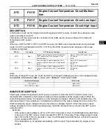
The Intake Air Temperature (IAT) sensor, mounted on the Mass Air Flow (MAF) meter, monitors the IAT.
The IAT sensor has a built-in thermistor with a resistance that varies according to the temperature of the
intake air. When the IAT drops, the resistance of the thermistor increases. When the temperature rises,
the resistance drops. These variations in resistance are transmitted to the ECM as voltage changes (See
Fig. 1).
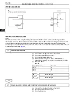
The IAT sensor is powered by a 5 V supply from the THA terminal of the ECM, via resistor R.
Resistor R and the IAT sensor are connected in series. When the resistance value of the IAT sensor
changes, according to changes in the IAT, the voltage at terminal THA also varies. Based on this signal,
the ECM increases the fuel injection volume when the engine is cold to improve driveability.
HINT:
When any of DTCs P0110, P0112 and P0113 are set, the ECM enters fail-safe mode. During fail-safe
mode, the IAT is estimated to be 20
°
C (68
°
F) by the ECM. Fail-safe mode continues until a pass condition
is detected.
DTC
P0110
Intake Air Temperature Circuit Malfunction
DTC
P0112
Intake Air Temperature Circuit Low Input
DTC
P0113
Intake Air Temperature Circuit High Input
DTC No.
Proceed to
DTC Detection Condition
Trouble Area
P0110
Step 1
Open or short in Intake Air Temperature (IAT)
sensor circuit for 0.5 seconds
(1 trip detection logic)
•
Open or short in IAT sensor circuit
•
IAT sensor (built into MAF meter)
•
ECM
P0112
Step 4
Short in Intake Air Temperature (IAT) sensor
circuit for 0.5 seconds (1 trip detection logic)
•
Short in IAT sensor circuit
•
IAT sensor (built into MAF meter)
•
ECM
P0113
Step 2
Open in Intake Air Temperature (IAT) sensor
circuit for 0.5 seconds (1 trip detection logic)
•
Open in IAT sensor circuit
•
IAT sensor (built into MAF meter)
•
ECM
Fig. 1
Resistance
Acceptable
Temperature
(kΩ)
(°C)
(°F)
A067628E20
Summary of Contents for 2GR-FE
Page 176: ...ES 20 2GR FE ENGINE CONTROL SYSTEM SFI SYSTEM ES NEXT 20 CONDUCT CONFIRMATION TEST END ...
Page 247: ...2GR FE ENGINE CONTROL SYSTEM SFI SYSTEM ES 91 ES OK REPLACE ECM See page ES 518 ...
Page 412: ...ES 256 2GR FE ENGINE CONTROL SYSTEM SFI SYSTEM ES A END ...
Page 447: ...2GR FE ENGINE CONTROL SYSTEM SFI SYSTEM ES 291 ES OK REPLACE ECM See page ES 518 ...
Page 556: ...ES 400 2GR FE ENGINE CONTROL SYSTEM SFI SYSTEM ES A REPLACE TCM ...
Page 630: ...ES 474 2GR FE ENGINE CONTROL SYSTEM SFI SYSTEM ES OK REPLACE ECM See page ES 518 ...
Page 658: ...2GR FE ENGINE CONTROL SYSTEM VVT SENSOR ES 493 ES 22 INSTALL ENGINE UNDER COVER LH ...
Page 897: ...2GR FE STARTING SMART KEY SYSTEM ST 35 ST OK REPLACE MAIN BODY ECU ...
Page 923: ...2GR FE STARTING SMART KEY SYSTEM ST 61 ST OK REPLACE MAIN BODY ECU ...
Page 935: ...2GR FE STARTING SMART KEY SYSTEM ST 73 ST OK REPLACE MAIN BODY ECU ...
Page 940: ...ST 78 2GR FE STARTING SMART KEY SYSTEM ST OK REPLACE MAIN BODY ECU ...
Page 958: ...ST 96 2GR FE STARTING SMART KEY SYSTEM ST OK END MAIN BODY ECU DEFECTIVE ...


