2GR-FE ENGINE CONTROL SYSTEM
– SFI SYSTEM
ES–263
ES
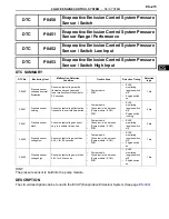
DTC SUMMARY
HINT:
The 0.02 inch orifice is located inside the pump module.
DESCRIPTION
The circuit description can be found in the EVAP (Evaporative Emission) System (See page
ES-400
).
INSPECTION PROCEDURE
Refer to the EVAP System (See page
ES-400
).
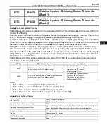
MONITOR DESCRIPTION
5 hours
*1
after the ignition switch is turned off, the electric vacuum pump creates negative pressure
(vacuum) in the EVAP (Evaporative Emission) system. The ECM monitors for leaks and actuator
malfunctions based on the EVAP pressure.
HINT:
*1
: If the engine coolant temperature is not below 35
°
C (95
°
F) 5 hours after the ignition switch is turned off,
the monitor check starts 2 hours later. If it is still not below 35
°
C (95
°
F) 7 hours after the ignition switch is
turned off, the monitor check starts 2.5 hours later.
DTC
P043E
Evaporative Emission System Reference Ori-
fice Clog Up
DTC
P043F
Evaporative Emission System Reference Ori-
fice High Flow
DTC
P2401
Evaporative Emission System Leak Detection
Pump Control Circuit Low
DTC
P2402
Evaporative Emission System Leak Detection
Pump Control Circuit High
DTC
P2419
Evaporative Emission System Switching Valve
Control Circuit Low
DTCs
Monitoring Items
Malfunction Detection Conditions
Trouble Areas
Detection
Timings
Detection
Logic
P043E
0.02 inch orifice clogged
P043E, P043F, P2401, P2402, P2419
are present when one of the following
conditions is met during key-off EVAP
monitor
•
Reference orifice clogged
•
Reference orifice high-flow
•
Leak detection pump OFF
malfunction
•
Leak detection pump ON
malfunction
•
Vent valve ON (close) malfunction
•
Pump module
•
Connector/wire
harness (Pump
module - ECM)
•
ECM
While
ignition
switch OFF
2 trip
P043F
0.02 inch orifice high-flow
P2401
Vacuum pump stuck OFF
P2402
Vacuum pump stuck ON
P2419
Vent valve stuck open
(vent)
Sequence
Operations
Descriptions
Duration
-
ECM activation
Activated by soak timer, 5 hours (7 or 9.5 hours) after ignition switch
turned off.
-
Summary of Contents for 2GR-FE
Page 176: ...ES 20 2GR FE ENGINE CONTROL SYSTEM SFI SYSTEM ES NEXT 20 CONDUCT CONFIRMATION TEST END ...
Page 247: ...2GR FE ENGINE CONTROL SYSTEM SFI SYSTEM ES 91 ES OK REPLACE ECM See page ES 518 ...
Page 412: ...ES 256 2GR FE ENGINE CONTROL SYSTEM SFI SYSTEM ES A END ...
Page 447: ...2GR FE ENGINE CONTROL SYSTEM SFI SYSTEM ES 291 ES OK REPLACE ECM See page ES 518 ...
Page 556: ...ES 400 2GR FE ENGINE CONTROL SYSTEM SFI SYSTEM ES A REPLACE TCM ...
Page 630: ...ES 474 2GR FE ENGINE CONTROL SYSTEM SFI SYSTEM ES OK REPLACE ECM See page ES 518 ...
Page 658: ...2GR FE ENGINE CONTROL SYSTEM VVT SENSOR ES 493 ES 22 INSTALL ENGINE UNDER COVER LH ...
Page 897: ...2GR FE STARTING SMART KEY SYSTEM ST 35 ST OK REPLACE MAIN BODY ECU ...
Page 923: ...2GR FE STARTING SMART KEY SYSTEM ST 61 ST OK REPLACE MAIN BODY ECU ...
Page 935: ...2GR FE STARTING SMART KEY SYSTEM ST 73 ST OK REPLACE MAIN BODY ECU ...
Page 940: ...ST 78 2GR FE STARTING SMART KEY SYSTEM ST OK REPLACE MAIN BODY ECU ...
Page 958: ...ST 96 2GR FE STARTING SMART KEY SYSTEM ST OK END MAIN BODY ECU DEFECTIVE ...


