ES–268
2GR-FE ENGINE CONTROL SYSTEM
– SFI SYSTEM
ES
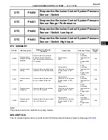
DTC SUMMARY
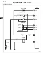
DESCRIPTION
The circuit description can be found in the EVAP (Evaporative Emission) System (See page
ES-400
).
INSPECTION PROCEDURE
Refer to the EVAP System (See page
ES-400
).
MONITOR DESCRIPTION
The two monitors, Key-off and Purge Flow, are used to detect malfunctions relating to DTC P0441. The
key-off monitor is initiated by the ECM internal timer, known as the soak timer, 5 hours* after the engine
switch is turned off. The purge flow monitor runs while the engine is running.
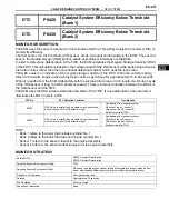
DTC
P0441
Evaporative Emission Control System Incorrect
Purge Flow
DTC No.
Monitoring Item
DTC Detection Condition
Trouble Area
Detection Timing
Detection
Logic
P0441
EVAP VSV
(Vacuum Switching
Valve) stuck open
Vacuum pump creates negative
pressure (vacuum) in EVAP
system and EVAP system
pressure measured. 0.02 inch
leak pressure standard measured
at start and at end of leak check.
If stabilized pressure higher than
[second 0.02 inch leak pressure
standard x 0.2], ECM determines
that EVAP VSV stuck open
•
EVAP VSV
•
Connector/wire harness
(EVAP VSV - ECM)
•
ECM
•
Pump module
•
Leakage from EVAP system
While engine
switch off
2 trip
P0441
EVAP VSV stuck
closed
After EVAP leak check
performed, EVAP VSV turned ON
(open), and atmospheric air
introduced into EVAP system.
0.02 inch leak pressure standard
measured at start and at end of
the check.
If pressure does not return to
near atmospheric pressure, ECM
determines that purge valve stuck
closed
•
EVAP VSV
•
Connector/wire harness
(EVAP VSV - ECM)
•
ECM
•
Pump module
•
Leakage from EVAP system
While engine
switch off
2 trip
P0441
Purge flow
While engine running, following
conditions are successively met:
•
Negative pressure not
created in EVAP system
when EVAP VSV turned ON
(open)
•
EVAP system pressure
change less than 0.5 kPa
(3.75 mmHg) when vent
valve turned ON (closed)
•
Atmospheric pressure
change before and after
purge flow monitor less than
0.1 kPa (0.75 mmHg)
•
EVAP VSV
•
Connector/wire harness
(EVAP VSV - ECM)
•
Leakage from EVAP line
(EVAP VSV - Intake manifold)
•
ECM
While engine
running
2 trip
Summary of Contents for 2GR-FE
Page 176: ...ES 20 2GR FE ENGINE CONTROL SYSTEM SFI SYSTEM ES NEXT 20 CONDUCT CONFIRMATION TEST END ...
Page 247: ...2GR FE ENGINE CONTROL SYSTEM SFI SYSTEM ES 91 ES OK REPLACE ECM See page ES 518 ...
Page 412: ...ES 256 2GR FE ENGINE CONTROL SYSTEM SFI SYSTEM ES A END ...
Page 447: ...2GR FE ENGINE CONTROL SYSTEM SFI SYSTEM ES 291 ES OK REPLACE ECM See page ES 518 ...
Page 556: ...ES 400 2GR FE ENGINE CONTROL SYSTEM SFI SYSTEM ES A REPLACE TCM ...
Page 630: ...ES 474 2GR FE ENGINE CONTROL SYSTEM SFI SYSTEM ES OK REPLACE ECM See page ES 518 ...
Page 658: ...2GR FE ENGINE CONTROL SYSTEM VVT SENSOR ES 493 ES 22 INSTALL ENGINE UNDER COVER LH ...
Page 897: ...2GR FE STARTING SMART KEY SYSTEM ST 35 ST OK REPLACE MAIN BODY ECU ...
Page 923: ...2GR FE STARTING SMART KEY SYSTEM ST 61 ST OK REPLACE MAIN BODY ECU ...
Page 935: ...2GR FE STARTING SMART KEY SYSTEM ST 73 ST OK REPLACE MAIN BODY ECU ...
Page 940: ...ST 78 2GR FE STARTING SMART KEY SYSTEM ST OK REPLACE MAIN BODY ECU ...
Page 958: ...ST 96 2GR FE STARTING SMART KEY SYSTEM ST OK END MAIN BODY ECU DEFECTIVE ...


