2GR-FE ENGINE CONTROL SYSTEM
– SFI SYSTEM
ES–393
ES
•
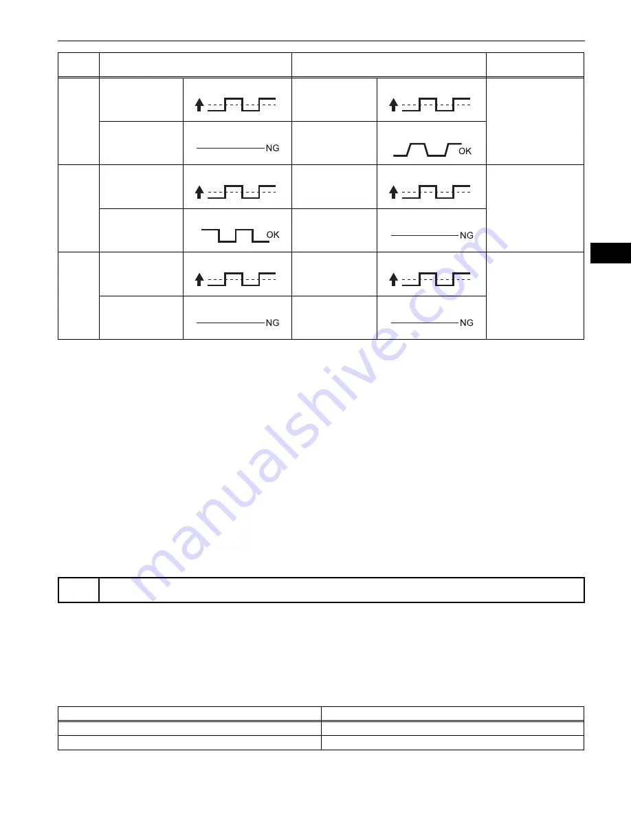
Following the A/F CONTROL procedure enables technicians to check and graph the voltage outputs of
both the A/F and HO2 sensors.
•
To display the graph, enter the following menus: DIAGNOSIS / ENHANCED OBD II / ACTIVE TEST /
A/F CONTROL / USER DATA / AFS B1 S1 and O2S B1 S2 or AFS B2 S1 and O2S B2 S2, and press
the YES button and then the ENTER button followed by the F4 button.
HINT:
•
DTC P2A00 or P2A03 may also be set, when the air-fuel ratio is stuck rich or lean.
•
A low A/F sensor voltage could be caused by a rich air-fuel mixture. Check for conditions that would
cause the engine to run rich.
•
A high A/F sensor voltage could be caused by a lean air-fuel mixture. Check for conditions that would
cause the engine to run lean.
•
Read freeze frame data using the intelligent tester. The ECM records vehicle and driving condition
information as freeze frame data the moment a DTC is stored. When troubleshooting, freeze frame
data can be helpful in determining whether the vehicle was running or stopped, whether the engine
was warmed up or not, whether the air-fuel ratio was lean or rich, as well as other data recorded at the
time of a malfunction (See page
ES-45
).
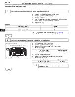
(a) Connect the intelligent tester to the DLC3.
(b) Turn the ignition switch on (IG).
(c) Turn the tester on.
(d) Enter the following menus: DIAGNOSIS / ENHANCED
OBD II / DTC INFO / CURRENT CODES.
(e) Read the DTCs.
Result
2
Injection Volume
+25 %
-12.5 %
Injection Volume
+25 %
-12.5 %
•
A/F sensor
•
A/F sensor heater
A/F sensor circuit
Output Voltage
Almost
no reaction
Output Voltage
More than 0.55 V
Less than 0.4 V
3
Injection Volume
+25 %
-12.5 %
Injection Volume
+25 %
-12.5 %
•
HO2 sensor
•
HO2 sensor heater
•
HO2 sensor circuit
Output Voltage
More than 3.35 V
Less than 3.0 V
Output Voltage
Almost
no reaction
4
Injection volume
+25 %
-12.5 %
Injection Volume
+25 %
-12.5 %
•
Fuel pressure
•
Gas leakage from
exhaust system
(Air-fuel ratio
extremely lean or
rich)
Output Voltage
Almost
no reaction
Output Voltage
Almost
no reaction
1
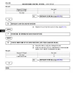
CHECK ANY OTHER DTCS OUTPUT (IN ADDITION TO DTC P2A00 AND/OR P2A03)
Case
A/F Sensor (Sensor 1)
Output Voltage
HO2 Sensor (Sensor 2)
Output Voltage
Main Suspected
Trouble Area
Display (DTC Output)
Proceed to
P2A00 and/or P2A03
A
P2A00 and/or P2A03 and other DTCs
B
Summary of Contents for 2GR-FE
Page 176: ...ES 20 2GR FE ENGINE CONTROL SYSTEM SFI SYSTEM ES NEXT 20 CONDUCT CONFIRMATION TEST END ...
Page 247: ...2GR FE ENGINE CONTROL SYSTEM SFI SYSTEM ES 91 ES OK REPLACE ECM See page ES 518 ...
Page 412: ...ES 256 2GR FE ENGINE CONTROL SYSTEM SFI SYSTEM ES A END ...
Page 447: ...2GR FE ENGINE CONTROL SYSTEM SFI SYSTEM ES 291 ES OK REPLACE ECM See page ES 518 ...
Page 556: ...ES 400 2GR FE ENGINE CONTROL SYSTEM SFI SYSTEM ES A REPLACE TCM ...
Page 630: ...ES 474 2GR FE ENGINE CONTROL SYSTEM SFI SYSTEM ES OK REPLACE ECM See page ES 518 ...
Page 658: ...2GR FE ENGINE CONTROL SYSTEM VVT SENSOR ES 493 ES 22 INSTALL ENGINE UNDER COVER LH ...
Page 897: ...2GR FE STARTING SMART KEY SYSTEM ST 35 ST OK REPLACE MAIN BODY ECU ...
Page 923: ...2GR FE STARTING SMART KEY SYSTEM ST 61 ST OK REPLACE MAIN BODY ECU ...
Page 935: ...2GR FE STARTING SMART KEY SYSTEM ST 73 ST OK REPLACE MAIN BODY ECU ...
Page 940: ...ST 78 2GR FE STARTING SMART KEY SYSTEM ST OK REPLACE MAIN BODY ECU ...
Page 958: ...ST 96 2GR FE STARTING SMART KEY SYSTEM ST OK END MAIN BODY ECU DEFECTIVE ...


