DIAGNOSIS SYSTEM
DESCRIPTION
The ECU contains a built–in self–diagnosis system by which
troubles with the engine signal network are detected and a
”CHECK” engine warning light on the instrument panel lights
up.
By analyzing various signals as shown in the table later on
(See page
) the Electronic Control Unit (ECU) detects
system malfunctions relating to the sensors or actuators.
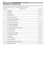
The self–diagnosis system monitors 19 (California specifica-
tion vehicles) or 17 (Other than California specification ve-
hicles) items, indicated by code No. as shown in
. A
”CHECK” engine warning light on the instrument panel in-
forms the driver that a malfunction has been detected. The
light goes off automatically when the malfunction has been
repaired. But the diagnostic code(s) remains stored in the
ECU memory (except for code Nos. 16, 51 and 53). The ECU
stores the code(s) until it is cleared by removing the EFI fuse
with the ignition switch off.
The diagnostic code can be read by the number of blinks of
the ”CHECK” engine warning light when TE1 and E1 termi-
nals on the TDCL or check connector are connected. When
2 or more codes are indicated, the lowest number (code) will
appear first.
TR–8
–
ENGINE TROUBLESHOOTING
Diagnosis System
Summary of Contents for 2VZ-FE
Page 1: ...ENGINE MECHANICAL EM 1 ENGINE MECHANICAL Description Operation ...
Page 31: ...CYLINDER HEADS COMPONENTS EM 29 ENGINE MECHANICAL Cylinder Heads ...
Page 63: ...CYLINDER BLOCK REMOVAL OF ENGINE EM 61 ENGINE MECHANICAL Cylinder Block ...
Page 64: ...EM 62 ENGINE MECHANICAL Cylinder Block ...
Page 71: ...COMPONENTS EM 69 ENGINE MECHANICAL Cylinder Block ...
Page 106: ...EFI SYSTEM FI 1 ...
Page 107: ...DESCRIPTION FI 2 EFI SYSTEM Description ...
Page 111: ...OPERATION System Circuit FI 4 EFI SYSTEM Operation System Circuit ...
Page 121: ...FUEL SYSTEM Fuel Pump EFI SYSTEM Fuel System Fuel Pump FI 15 ...
Page 141: ...Fuel Tank and Lines COMPONENTS EFI SYSTEM Fuel System Fuel Tank and Lines FI 35 ...
Page 172: ...EXHAUST SYSTEM EXHAUST SYSTEM REPAIR INSTRUCTIONS EX 1 ...
Page 174: ...EMISSION CONTROL SYSTEMS EC 1 ...
Page 186: ...COOLING SYSTEM CO 1 ...
Page 205: ...LUBRICATION SYSTEM LUBRICATION SYSTEM Description Operation LU 1 ...
Page 224: ...IGNITION SYSTEM IG 1 ...
Page 237: ...SERVICE SPECIFICATIONS IG 14 IGNITION SYSTEM ServiceSpecifications ...
Page 238: ...ENGINE TROUBLESHOOTING TR 1 ...


