background image

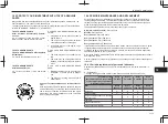
18 PLANNED MAINTENANCE

en‐80

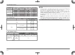
Inspection Period

(Accumulated hours of operation

or monthly periods of operation,

whichever comes sooner.)

Every

6 weeks

Every

3 months

Every

6 months

Every

12 months

Item

Every

250 hours

Every

500 hours

Every

1000 hours

Every

2000 hours

Differential gear oil

Planetary gear oil

Hydraulic oil

Hydraulic oil filter

●*

Wheel bearing grease

Spark plugs

Air cleaner element

Cups  and  seals  for  brake  booster
and wheel cylinders

Power steering hoses

Every 2 years

Power steering rubbers parts

Every 2 years

Hydraulic hoses

Every 2 years

Fuel hoses

Every 2 years

Torque converter rubber hoses

Every 2 years

O­ring for LPG tank valve (Option)

Every 2 years

LPG  high  and  low­pressure  rubber
hoses (Option)

Every 2 years

LPG  regulator  diaphragm  and  gas­
ket, O­ring (Option)

Every 2 years

LPG  filter  &  shut­off  valve  dia­
phragm and gasket (Option)

Every 2 years

Chains

Every 3 years

Timing belt of 1KD *

1

Every 4000 hours

Hydraulic oil pump seal

Every 3 years or 6000 hours

SAS Swing lock cylinder

Every 10000 hours

*

1

: The timing belt caution function will inform the operator when the timing belt needs to be

replaced. Refer to the INSTRUMENT chapter of this manual for details.

NOTICE! In case of the harsh or severe operating condition, the service interval of 170
hours or 1 month may be recommended.

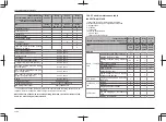
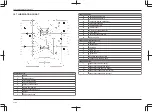
18.4.2 Periodic maintenance table

INSPECTION METHOD

I : Inspection. Repair or replacement if required. 
M : Measurement. Repair or adjustment if required. 
T : Retightening
C : Cleaning
L : Lubrication
*: Same as the left column
*

1

: For new truck

*

2

: Fissure and crack detector

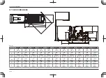
Inspection Period

(Based on operating hours or months, whichever is

soonest.)

Every

6

weeks

Every

3

months

Every

6

months

Every

12

months

Item

Every

250

hours

Every

500

hours

Every

1000

hours

Every

2000

hours

ENGINE

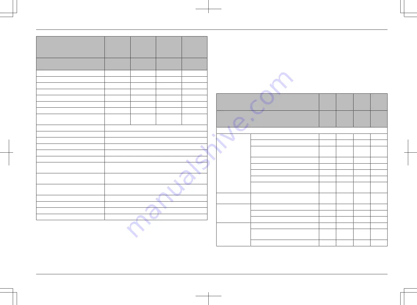
Basic 

compon­

ents

Proper starting and abnormal noise

I*

1

I

*

*

Rotating condition at idling

M*

1

M

*

*

Rotating  condition  during  accelera­
tion

M*

1

M

*

*

Exhaust gas condition

I*

1

I

*

*

Air cleaner element

C*

1

C

*

*

Valve clearance

M*

1

M

Muffler rubber mount

I

Engine  ancillary  drive  belt  tension,
looseness and damage

I

*

*

*

PCV system

Clogging  and  damage  in  PCV  valve
and piping

I*

1

I

*

*

Lubrication 

sys­

tem

Oil leak

I*

1

I

*

*

Oil level

I*

1

I

*

*

Clogging and dirt of oil filter

I

*

*

Fuel system

Fuel leak

I*

1

I

*

*

Dirt  and  clogging  of  fuel  filter  ele­
ment

I

*

*

Draining of sedimenter

I

*

Summary of Contents for 40--8FD35N

Page 1: ...Key off head light off system Option en 23 10 11 Torque converter interlock function Option en 23 10 12 Tilt steering adjust lever en 23 10 13 Pedals en 24 10 14 EZ pedal Option en 24 10 15 Horn butto...

Page 2: ...FUEL SYSTEM en 70 16 5 DRAINING THE SEDIMENTER en 70 16 6 ADJUSTMENT OF THE PARKING BRAKE OPERATING FORCE en 71 16 7 MAINTAINING THE BATTERY TERMINALS en 71 16 8 CLEANING PRE CLEANER OPTION en 71 16...

Page 3: ...is manual thoroughly even though you may already be familiar with our forklift trucks because it contains information which is exclusive to this series of trucks This manual is based on a standard tru...

Page 4: ...ay impact stability and may cause the fork lift to tip over When travelling maintain a fork height above the ground of 10 20cm 6 8 inches Please avoid overloading or uneven loading Overloading or an u...

Page 5: ...S en 6 3 MAIN COMPONENTS 4 9 12 7 13 8 10 1 Mast 8 Counterweight 2 Chain 9 Engine hood 3 Forks 10 Steering wheel 4 Lift cylinder 11 Operator s seat 5 Tilt cylinder 12 Drive axle 6 Overhead guard 13 St...

Page 6: ...ction control lever 8 Tilt lever knob switch 14 Ignition key switch 3 Steering wheel 9 Attachment lever Option 15 Inching pedal 4 Horn button 10 Multi function display Option 16 Tilt steering adjustin...

Page 7: ...ration The sample shows that of an English version B B A 1 2 3 4 5 6 8 7 13 9 8 7 10 11 12 12 12 11 11 1 Truck model 2 Code No of special model model of attachment 3 Frame No special number for the tr...

Page 8: ...n lifting the truck don t risk dropping the truck never use the overhead guard to pick it up Use the counterweight to lift the truck c Refer to the warning label for the sound power level of the truck...

Page 9: ...your truck tips stay in the seat lean away from the tipping direction hang on and brace your feet i This truck is equipped with SAS Be sure to read and follow the instruction in the SAS FUNCTION secti...

Page 10: ...look for it espe cially on the mast and on attachments When you see it stay clear Models with optional Cabin Rear window of the Cabin can be opened by releasing the lock lever at the bottom of the win...

Page 11: ...the truck should not be operated until it has been repaired While operating a truck equipped with SAS should the diagnosis indicator lamp illuminate or an error code be indicated on the display park...

Page 12: ...backward position while pressing the tilt lever knob switch the forks will Not Loaded Loaded High Lift Height Over 6 feet or 2 m Stop at the horizontal position with mast vertically positioned Stop a...

Page 13: ...ven if the lift lever is operated The forks can be lowered when the operator is seated in the operator s seat and key switch is turned on ACTIVE STEERING CONTROL If the steering wheel knob is not at t...

Page 14: ...ll illuminate and load handling operations will be stopped If the operator returns to normal seating position within 2 seconds lowering operation can be continued If the operator leaves the seat while...

Page 15: ...t released prior to travel the parking brake on warning indicator will blink on the Multi function display and the warning sound will warn the operator 8 6 Parking brake off warning If the operator le...

Page 16: ...lti function display by the operator and a supervisor For details refer to INSTRUMENT section of this manual 9 2 Engine auto stop function Option Multi function Display DX If the operator leaves the t...

Page 17: ...When starting 1FS engine models gasoline LPG do not press the accelerator pedal Do not leave the key switch in the ON position when the engine is stopped It will cause the battery to over discharge Do...

Page 18: ...k the lever while pressing the release knob button While operating the parking brake lever keep the brake pedal fully depressed WARNING Before applying the parking brake depress the brake pedal and al...

Page 19: ...will not lower even if the lever is moved to the lower ing position When you sit in the normal seated position and turn the key switch to ON po sition you can lower the forks even if the engine is sto...

Page 20: ...at a low lift height by pressing the knob switch At a high lift height the backward tilting speed is automatically re duced by the active mast backward tilt speed control function of SAS For details o...

Page 21: ...OFF ON Tail lights clearance lights Option ON ON Meter illumination light ON ON CAUTION Do not keep lights such as the head lights on for a long time when the engine is stopped It may cause over disc...

Page 22: ...ection control lever after travel speed is reduced sufficiently Ask the Toyota dealer about changing the speed setting CAUTION When the interlock is engaged release the accelerator pedal and use the b...

Page 23: ...pedal depressed NOTICE After the OPS is activated the OPS can be canceled by sitting in the seat and applying the parking brake or releasing the accelerator pedal and pressing it again 10 15 Horn butt...

Page 24: ...travel Shift the lever to change the travel direction between forward and reverse Forward travel Push the lever forward Reverse travel Pull the lever backward The neutral position is halfway between t...

Page 25: ...lt lever is moved WARNING Always operate the tilt lever from a normal seated position If the OPS is activated fully release the accelerator pedal return all levers to the neutral position and return t...

Page 26: ...er the activation of OPS release the accelerator pedal return the direction control lever to the neutral position and sit in the seat Sitting in the seat without returning the direction control lever...

Page 27: ...turn all levers to the neutral position and return to the normal seated position to deactivate the OPS After the OPS is activated if you return to the normal seated position while the lever s are oper...

Page 28: ...to place it to a desired position 3 Turn knob clockwise to lock 1 1 Lever for turning and securing the arm rest Tilt adjustment 1 Pull up and loosen the lever for turning and securing the arm rest 2 A...

Page 29: ...witch prevents powered traveling and load handling operations when the operator is not seated in the seat Be sure to remain seated in the seat while in operation Do not operate the truck with any obje...

Page 30: ...Normal traveling position with lock 4 Traveling in reverse position with lock The swivel seat is useful when traveling in the reverse direction over long distances or when getting off the truck The s...

Page 31: ...seat and seat belt will help to keep you safely within the truck and operator s compartment In the event of a tip over don t jump grip the steering wheel brace your feet lean away from the direction...

Page 32: ...he hood slightly to check that the hood damper has been securely locked before letting go Opening Models with Cabin Mini lever or Joy stick 1 Pull up the seat slide lever and slide the seat to the for...

Page 33: ...uard WARNING When lifting the truck at lifting points be sure to use cable that has plenty of strength 11 8 Overhead guard When properly maintained the overhead guard will help protect the operator fr...

Page 34: ...position to keep the forks in place WARNING Make sure the forks are securely locked before carrying a load WARNING Forks are heavy Caution is required when sliding a fork on the carriage as it may bec...

Page 35: ...ndicator Diesel engine models 7 Malfunction indicator lamp 8 Engine oil pressure warning 9 Charging system warning 10 OPS indicator 11 Diagnosis indicator 12 Air cleaner warning Option OK monitor 13 C...

Page 36: ...eter will be alternately displayed CAUTION Should an error code be displayed park the truck in a safe location apply parking brake remove the key and ask the Toyota dealer for an inspection When the t...

Page 37: ...endation Use only ultra low sulfur fuel defined by EN590 2013 which contains a sulfur not more than 10 ppm and a cetane index of 46 or more NOTICE In cold weather use winter diesel fuel to prevent clo...

Page 38: ...ing lamp comes on while the engine is running stop the operation im mediately park the truck in a safe loca tion Stop the engine apply the parking brake and remove the key After the en gine has cooled...

Page 39: ...1 12 OK monitor Option 1 Air cleaner warning 2 Cooling water level warning 3 Brake indicator This function monitors the air cleaner ele ment clogging status engine coolant level battery fluid level an...

Page 40: ...ve conditions occur park the truck in a safe location apply the parking brake and contact the Toyota dealer immedi ately CAUTION Once the timing belt caution function is on have the timing belt replac...

Page 41: ...peedometer 2 Torque converter oil temperature indicator Truck speed is digitally indicated in km h in the middle of the screen At the bottom of the screen torque converter oil temperature is indicated...

Page 42: ...aler 12 2 7 Diagnosis indicator MODE The diagnosis indicator and the error code will be displayed when an error is found and a warning sound will warn the operator NOTICE The error code displayed on t...

Page 43: ...conds each time the lift lever is returned to neutral position The load weight is not displayed when the traveling speed is detected To change the display time ask the Toyota dealer This function shou...

Page 44: ...nds to notify the operator When the torque converter oil temperature reaches level 10 approx 135 C 275 F or over the entire indicator will blink to notify the operator If the accelerator pedal is pres...

Page 45: ...perator setting menu screen Low speed setting screen Over speed alarm setting screen Switch a Switch d Press switch a on the status screen for more than 2 seconds to display the Operator setting menu...

Page 46: ...set over 32km h the low speed setting is disabled In this case OFF is displayed 12 2 16 2 Over speed alarm setting screen Models with Multi function Display DX MODE 1 Switch b 2 Switch c 3 Switch d T...

Page 47: ...NOTICE If the key switch is turned off fuel is not supplied to the engine even when the fuel changeover switch is positioned at LPG or GAS position LPG warning switch Option 1 1 LPG warning switch Whe...

Page 48: ...es during use Pipe valve When the fuel hose needs to be disconnec ted for tank replacement etc close this valve to prevent the liquid from running out of the hose To open the valve turn it countercloc...

Page 49: ...n the engine hood according to in structions in BODY COMPONENTS chapter Closing Close the engine hood according to instruc tions in BODY COMPONENTS chapter 13 4 Operating LPG powered forklift Starting...

Page 50: ...Refrain from handling and driving the truck roughly especially when it is new Parking CAUTION Park LPG powered trucks only in well ventilated area When parking for a short time 1 For Gasoline LPG mode...

Page 51: ...ective equipment when replacing the LPG tank LPG can freeze hands and fin gers in case the gas leaks 1 Stop the engine according to instructions for When parking for a long time 2 Turn the pipe valve...

Page 52: ...LPG DEVICE OPTION en 53 Swing type Swing down type 7 Pull the tank clamp toward you and unlock the tank bands Swing type Swing down type 8 Raise the tank bands away from you and remove the LPG tank 1...

Page 53: ...e upward or rearward Swing type Swing down type 2 Put bands over the tank hook clamps to bands and push clamps up to clamp the tank 1 1 Set pin lower side 3 For swing down type unlock the tank bracket...

Page 54: ...LPG powered forklifts LPG is flammable A tiny spark can cause a fatal explosion if it is handled carelessly It is very crucial that the following precautions are observed most strictly to avoid hazar...

Page 55: ...er 4 Rear glass 14 1 Doors 1 1 Door handle Outside the truck 1 Pull the door handle to release the lock and open the door 2 When closing the door press until the door lock catches Both doors can be lo...

Page 56: ...w Hold the assist lever and push the window back to open the window to ventilation mode 2 Push the assist lever further back to ex tend the damper and the window will be opened to maintenance mode 3 T...

Page 57: ...may cause over discharge of the battery and make engine starting im possible Using the heater for extended periods of time will cause the air inside the cabin to be come stale and the glass to fog so...

Page 58: ...age cut or frayed straps loose stitching tongue damage buckle and retractor damage 15 1 Walkaround inspection 15 1 1 Alignment Does the truck lean to one side or the other If so check for flat tire or...

Page 59: ...y coolant to the upper limit 3 The concentration of the long life coolant LLC in the engine coolant must be 50 NOTICE If no engine coolant remains in the reservoir tank be sure to check the coolant le...

Page 60: ...t without pushing the oil cap in NOTICE The oil level varies with the maximum lift height 5 If the oil level is insufficient add oil Spilled and splashed oil must be wiped off thoroughly Identificatio...

Page 61: ...rules Turn the key switch and lights off Check for leaks only in well ventilated approved areas No smoking fire of flames allowed Make certain that there is no source of fire in the area throughout th...

Page 62: ...anually depress the brake pedal to check the play until a resistance is felt NOTICE See the Service Data section of this manual for the amount of brake pedal play WARNING Ask the Toyota dealer for an...

Page 63: ...4 Parking brake inspection Check the operating force required for pulling the parking brake lever NOTICE See the Service Data section of this manual for the parking brake operat ing force WARNING Ask...

Page 64: ...d when cold The engine re sumes normal speed when it is fully warmed 1 Start the engine and warm it up suffi ciently 2 Check each meter and warning lamp to see if there is any problem 3 Check if the e...

Page 65: ...ck slowly in a safe location turn the steering wheel to the left and right and check for any unusual movement 15 4 3 Brake effectiveness Inspect to see if there is anything unusual when the inching an...

Page 66: ...89 octane RON89 rating or higher NOTICE Do not use gasoline with more than 10 Ethanol E10 or engine fuel system damage may occur Do not use deteriorated fuel which has been stored for a long period of...

Page 67: ...r jack stands after jack ing up 4 Jack up until the wheels come off the ground Completely remove the air pres sure from the tire then remove the hub nuts and remove the wheel 5 To reinstall the wheel...

Page 68: ...Engine P 15A HEAD LIGHT EDU 1KD Engine Q 7 5A MATCH E 20A EFI 1FS Engine R 7 5A START F 20A ACC B S 10A GAUGE G 10A ACC B2 T 10A BACK LIGHT H 7 5A ALT S U 7 5A SHIFT I 7 5A STOP V 7 5A TURN J 7 5A TA...

Page 69: ...f the sedimenter fuel filter warning lamp comes on immediately drain water ac cording to the following procedure because the accumulated water in the sedimenter is above the specified level 1 Place a...

Page 70: ...eplace it last 1 Grease 1 A loose or corroded terminal causes fail ure in connection Remove white powder if any from the terminal by pour ing warm water over it to dissolve it and then apply grease on...

Page 71: ...as near to the truck as necessary for the jumper cables to reach both batteries Check and make sure that the trucks do not touch each other Apply the parking brake Put the control levers in the neutr...

Page 72: ...ons when lifting the forklift Lift the forklift using the lifting points The lifting points are indicated on the warning labels attached to the forklift Use a wire cable or strap which has the capacit...

Page 73: ...section of the manual inspect the trucks thoroughly to insure safety and pleasant working conditions Have necessary adjustments or replacements performed by qualified service staff or at the Toyota d...

Page 74: ...or damaged NOTICE Wash the element if heavily contaminated How to wash the element 1 Soak the element in water containing mild detergent for approximately 30 minutes and then wash Use care not to scra...

Page 75: ...1 1 Electrolyte level indicator 1 Use the electrolyte level indicator to check the battery condition 2 The indicator shows green color if the electrolyte level is normal white if the level is low and...

Page 76: ...inspections after 30 seconds and within five minutes after the engine has stopped 5 If the level is near or below the L line add oil to the F line Use only oil specified in the lubrication table 2 3 2...

Page 77: ...Set the fuel changeover switch to the OFF position Gasoline LPG models and open the engine hood 2 Put an oil pan under the regulator hose Open the plug or the drain cock Option and let tar drop into t...

Page 78: ...ine parts 18 4 PERIODIC MAINTENANCE AND REPLACEMENT Periodic inspection and maintenance are necessary to keep your Toyota industrial truck running safely and smoothly The maintenance experts at the To...

Page 79: ...ll inform the operator when the timing belt needs to be replaced Refer to the INSTRUMENT chapter of this manual for details NOTICE In case of the harsh or severe operating condition the service interv...

Page 80: ...ft Loose joint I Looseness at spline connections I Looseness of universal joint I Twisting and cracks of axle shaft I Inspection Period Based on operating hours or months whichever is soonest Every 6...

Page 81: ...ness I Wear and damage of mast support bushing I Wear damage and rotating condi tion of rollers I Wear and damage of roller pins I Wear and damage of mast channel I Inspection Period Based on operatin...

Page 82: ...S Overhead guard Cracks at welded portion I Deformation and damage I Back rest Loosening of mounting T Deformation crack and damage I Inspection Period Based on operating hours or months whichever is...

Page 83: ...ry 6 weeks Every 3 months Every 6 months Every 12 months Item Every 250 hours Every 500 hours Every 1000 hours Every 2000 hours Others Grease See the LUBRICATION CHART of this manual L NOTICE In case...

Page 84: ...5 6 0 8 0 ton 2600 35 BATTERY Battery electrolyte specific gravity at 20 C 68 F 1 280 STEERING Steering wheel play at engine idle speed mm in 25 50 1 0 2 0 BRAKE Brake pedal mm in Play 3 7 0 12 0 28 F...

Page 85: ...e with EN 12053 Uncertainty K 4 dB A dB A Standard 80 77 79 Cabin Models 75 NOTICE The sound pressure values shown above can be used as the sound level at operators ears Values are in accordance with...

Page 86: ...3 8 4 5 5 0 ton 120 31 7 6 0 8 0 ton 130 34 3 Chassis parts All models Proper quantity MP grease Molybdenum disulfide grease Engine cooling system excluding re serve tank Gasoline 1FS 12 0 3 2 LLC Lon...

Page 87: ...axle beam front pin 11 Rear axle beam rear pin 12 Tilt steering locking mechanism 13 Mast support bushing 14 Tilt cylinder front pin 15 Propeller shaft 16 Swing lock cylinder lower pin 17 Tie rod end...

Page 88: ...NCE en 89 18 8 FRAME SERIAL NUMBER 1 1 Frame serial number Frame serial number location The frame serial number is stamped on the left mud guard Refer to the frame serial number when making inquiries...

Page 89: ...1 1450 57 1 1965 77 4 1965 77 4 1965 77 4 B2 B4 1170 300 46 1 11 8 1170 300 46 1 11 8 1170 300 46 1 11 8 1170 300 46 1 11 8 1160 300 45 7 11 8 1160 300 45 7 11 8 1160 300 45 7 11 8 1160 300 45 7 11 8...

Page 90: ...53 1 h9 420 16 5 420 16 5 420 16 5 420 16 5 420 16 5 420 16 5 420 16 5 420 16 5 485 19 1 485 19 1 485 19 1 L 1000 39 1000 39 1000 39 1000 39 1000 39 1000 39 1200 47 1200 47 1200 47 1200 47 1200 47 L1...

Page 91: ...0 6150 6610 6690 7140 7220 8360 9090 9940 Front axle load with load 8670 8690 9360 9380 10430 10450 10880 10910 12850 14330 15860 Front axle load without load 2550 2570 2480 2500 2830 2850 3000 3030 3...

Page 92: ...19 TRUCK DIMENSIONS en 93 19...

Reviews: