7-132
7 DISPLAY
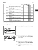
2. MINI LEVER
No.
Indication
Description
Prerequisite for im-
plementation
1
LEVER1
Lift lever angle sensor output value in the lift lever neut-
ral position is stored in the controller.
*1, *9
2
LEVER2
Tilt lever angle sensor output value in the tilt lever neut-
ral condition is stored in the controller.
*1, *10
3
LEVER3
Attachment (1) lever angle sensor output value in the at-
tachment (1) lever neutral position is stored in the con-
troller.
*1, *11
4
LEVER4
Attachment (2) lever angle sensor output value in the at-
tachment (2) lever neutral position is stored in the con-
troller.
*1, *12
3. EMRV
No.
Indication
Description
Prerequisite for im-
plementation
1
C01
Electromagnetic relief valve solenoid current L level
*1, *13
2
C02
Electromagnetic relief valve solenoid current H level
*1, *13
Prerequisite content for implementation
*1: SAS/OPS controller replacement
*9: When replacing lift lever angle sensor
*10: When replacing tilt lever angle sensor
*11: When replacing attachment (1) lever angle sensor
*12: When replacing attachment (2) lever angle sensor
*13: When removing/installing or replacing oil control valve
7.2.6.3 BEFORE STARTING MATCHING
Set the vehicle to "Standard vehicle condition" before starting matching.
"Standard vehicle condition" means that the vehicle satisfies the conditions described below.
Standard vehicle condition
NOTICE:
▪
Items 1 to 4 below show the standard vehicle condition for SAS matching.
▪
Before carrying out matching for mini lever/joystick vehicles, move the armrest to the driving po-
sition and check the neutral state of the levers.
▪
In case of a detachable attachment, keep the attachment installed on the vehicle.
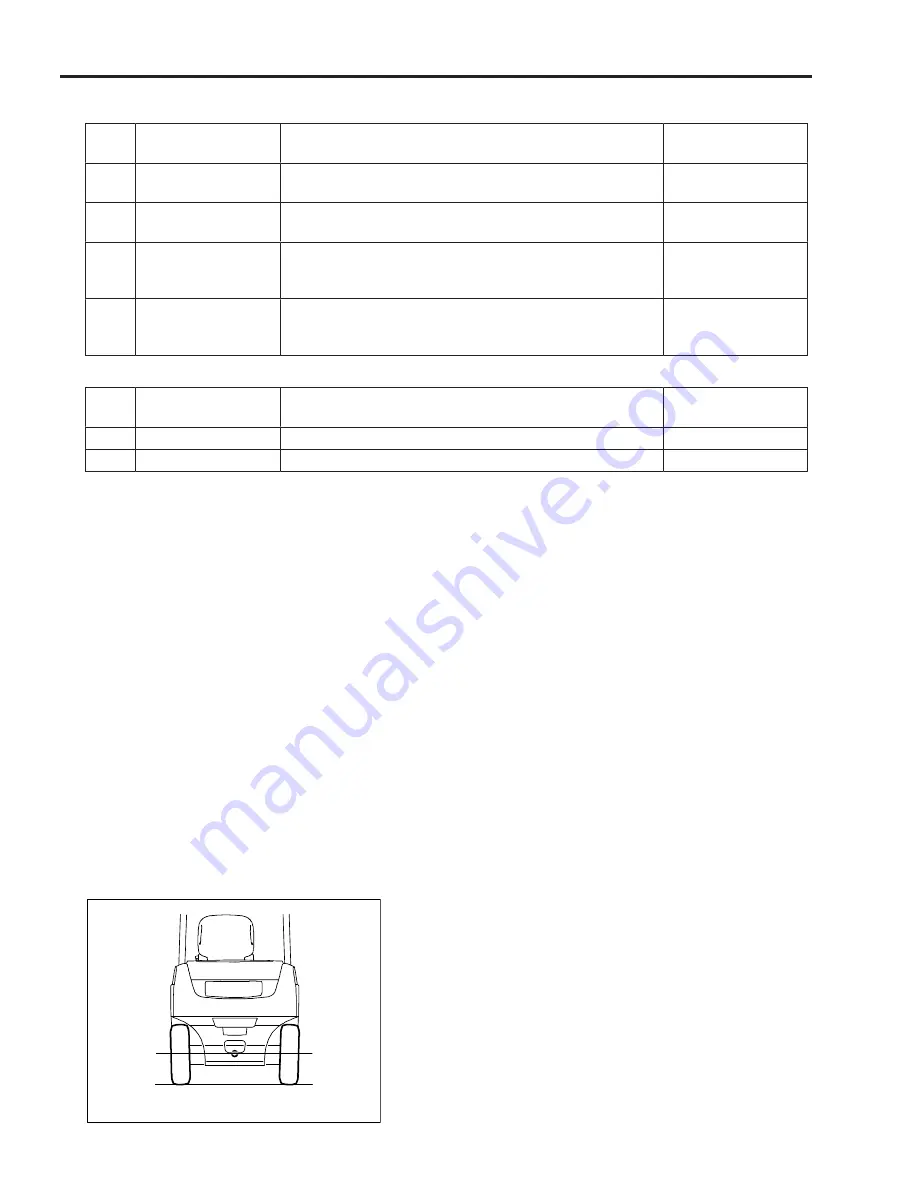
Level surface
1. Tire pressure check
Adjust the tire pressure to the specified level. Match-
ing will be inaccurate if the pressure is low, or if there
are air pressure fluctuations between front and rear
as well as left and right.
2. Surface levelness check
If matching is conducted on an inclined or rough floor
surface, errors in standard vehicle condition will oc-
cur, so perform matching on a flat, level surface (in-
clination: within 0.5°).
Summary of Contents for 62-8FDU15
Page 5: ...1 3 1 GENERAL 1 2 FRAME NUMBER Frame No Punching Position Punching position 1...
Page 8: ...2 6 2 STEERING 4YM and 1DZ engine W synchronized steering B B A A B B C C C C...
Page 11: ...2 9 2 STEERING 2 3 COMPONENTS 1ZS and 4YE engine 4507 4YM and 1DZ II engine 4507 2...
Page 13: ...2 11 2 STEERING 4YM and 1DZ II engine W synchronized steering 4503 2...
Page 23: ...3 21 3 MATERIAL HANDLING SYSTEM 3 2 COMPONENTS 6801 3...
Page 46: ...5 44 5 OIL CONTROL VALVE 5 2 3 COMPONENTS 1ZS and 4YE engine ASSY FITTING 6705...
Page 55: ...6 53 6 SAS OPS 6...
Page 56: ...6 54 6 SAS OPS Load Sensor 1DZ II engine 5803...
Page 157: ...8 155 8 TROUBLESHOOTING 8 3 WHEN NO ERROR CODE IS DISPLAYED Defect causes related to SAS OPS 8...
Page 191: ...8 189 8 TROUBLESHOOTING 8 4 WHEN ERROR CODE IS DISPLAYED 8...
Page 221: ...Published by 1st Printing Mar 2016 Pub No CE118 Printed in USA...
Page 222: ...PRINTED IN USA Pub No CE118...


