2-14
2 STEERING
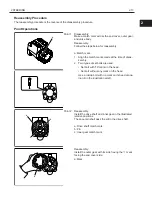
a
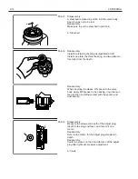
A
Point 3
Disassembly:
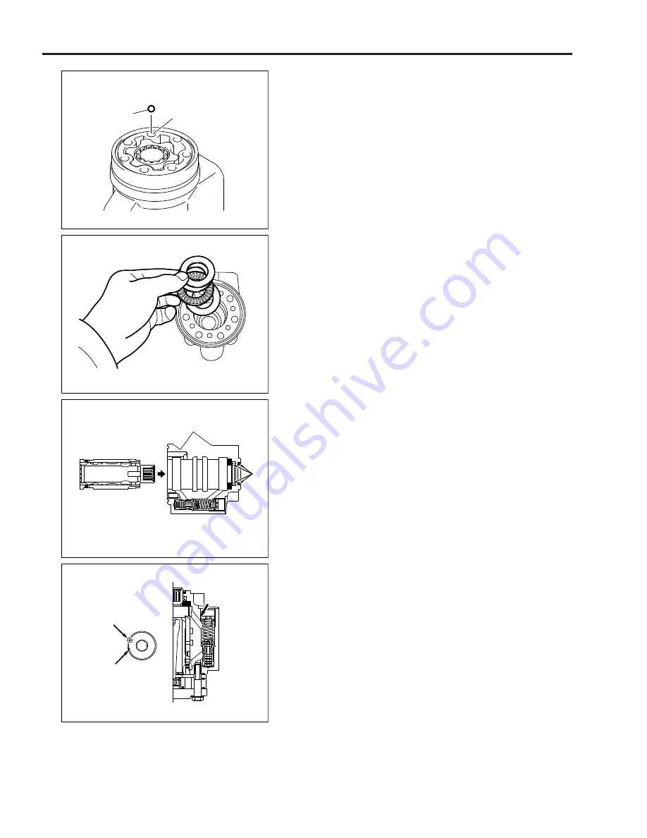
A steel ball is placed in portion A of the valve body.
Keep it so as not to be lost.
Reassembly:
Make sure to put the steel ball in portion A.
a: Steel ball
Point 4
Reassembly:
Install the retaining bearing as illustrated at left.
Install one plate, the thrust bearing, and two plates in
this order from the depth.
Reassembly:
When inserting the sleeve W/ spool into the valve
body, apply MP grease to the packing, ring inner sur-
face (portion in sliding contact with the spool), and
dust seal lip.
a
Point 5
Disassembly:
Measure the screwed-in depth of the adjust plug
(depth to the plug end face), and record it on a
memo.
Reassembly:
Refer to the memo for the adjust plug screwed-in
depth.
Reassembly:
Caulk two places on the circumference of the adjust
plug after hydraulic pressure adjustment.
a: Caulk
Summary of Contents for 62-8FDU15
Page 5: ...1 3 1 GENERAL 1 2 FRAME NUMBER Frame No Punching Position Punching position 1...
Page 8: ...2 6 2 STEERING 4YM and 1DZ engine W synchronized steering B B A A B B C C C C...
Page 11: ...2 9 2 STEERING 2 3 COMPONENTS 1ZS and 4YE engine 4507 4YM and 1DZ II engine 4507 2...
Page 13: ...2 11 2 STEERING 4YM and 1DZ II engine W synchronized steering 4503 2...
Page 23: ...3 21 3 MATERIAL HANDLING SYSTEM 3 2 COMPONENTS 6801 3...
Page 46: ...5 44 5 OIL CONTROL VALVE 5 2 3 COMPONENTS 1ZS and 4YE engine ASSY FITTING 6705...
Page 55: ...6 53 6 SAS OPS 6...
Page 56: ...6 54 6 SAS OPS Load Sensor 1DZ II engine 5803...
Page 157: ...8 155 8 TROUBLESHOOTING 8 3 WHEN NO ERROR CODE IS DISPLAYED Defect causes related to SAS OPS 8...
Page 191: ...8 189 8 TROUBLESHOOTING 8 4 WHEN ERROR CODE IS DISPLAYED 8...
Page 221: ...Published by 1st Printing Mar 2016 Pub No CE118 Printed in USA...
Page 222: ...PRINTED IN USA Pub No CE118...


