5-49
5 OIL CONTROL VALVE
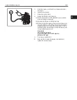
Point 7
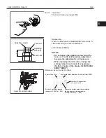
Inspection:
Check and clean any clogged filter.
a
Adjusting screw A
Lock nut 1
Adjusting
sleeve B
Lock nut 2
Reassembly:
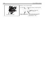
When the relief valve is disassembled, temporarily in-
stall it after fitting the nuts as illustrated.
a = 27.0 mm (1.06 in)
NOTICE:
▪
Do not loosen the adjusting screw A and the
lock nut 1 for tilt relief pressure adjustment
because the adjustment is not necessary.
▪
When replacing the relief valve, change the
setting value (H and L rank) it is necessary.
(Refer to chapter of the display for MATCHING
EMRV "EMRV")
Level of current to plate
Reference: level of current to plate
4 unit of short No.
5 unit serial No. and whose 5 unit start from 00001
Stamp 3 unit aim pressure
Mention I-P current rank
(H-L each 1unit)
Stamp the current value that calculated
than an approximate expression
(example: 3.5 MPa → 035)
(example: 590 mA → 590)
5
Summary of Contents for 62-8FDU15
Page 5: ...1 3 1 GENERAL 1 2 FRAME NUMBER Frame No Punching Position Punching position 1...
Page 8: ...2 6 2 STEERING 4YM and 1DZ engine W synchronized steering B B A A B B C C C C...
Page 11: ...2 9 2 STEERING 2 3 COMPONENTS 1ZS and 4YE engine 4507 4YM and 1DZ II engine 4507 2...
Page 13: ...2 11 2 STEERING 4YM and 1DZ II engine W synchronized steering 4503 2...
Page 23: ...3 21 3 MATERIAL HANDLING SYSTEM 3 2 COMPONENTS 6801 3...
Page 46: ...5 44 5 OIL CONTROL VALVE 5 2 3 COMPONENTS 1ZS and 4YE engine ASSY FITTING 6705...
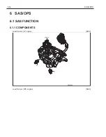
Page 55: ...6 53 6 SAS OPS 6...
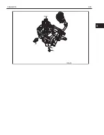
Page 56: ...6 54 6 SAS OPS Load Sensor 1DZ II engine 5803...
Page 157: ...8 155 8 TROUBLESHOOTING 8 3 WHEN NO ERROR CODE IS DISPLAYED Defect causes related to SAS OPS 8...
Page 191: ...8 189 8 TROUBLESHOOTING 8 4 WHEN ERROR CODE IS DISPLAYED 8...
Page 221: ...Published by 1st Printing Mar 2016 Pub No CE118 Printed in USA...
Page 222: ...PRINTED IN USA Pub No CE118...


