5-51
5 OIL CONTROL VALVE
5.
Start the engine, and check for oil leaks and abnor-
mal noise.
6.
Install the toe board.
7.
Close the engine hood.
8.
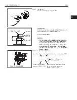
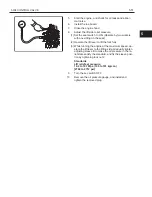
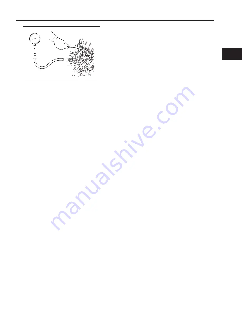
Adjust the lift side relief pressure.
(1) Set the seat switch to ON. (Operate by two workers
with one sitting on the seat.)
(2) Operate the lift lever to lift the fork fully.
(3) While running the engine at the maximum speed, op-
erate the lift lever to the lifting side. Gradually tighten
adjusting sleeve B to make the oil pressure in the re-
lief state satisfy the standard, and fix the sleeve posi-
tion by tightening lock nut 2.
Standards
Lift relief set pressure:
19.2 to 18.7 Mpa
(196 to 191 kg/cm
2
)
[2784 to 2712 psi]
9.
Turn the key switch OFF
10.
Remove the oil pressure gauge, and install and
tighten the removed plug.
5
Summary of Contents for 62-8FDU15
Page 5: ...1 3 1 GENERAL 1 2 FRAME NUMBER Frame No Punching Position Punching position 1...
Page 8: ...2 6 2 STEERING 4YM and 1DZ engine W synchronized steering B B A A B B C C C C...
Page 11: ...2 9 2 STEERING 2 3 COMPONENTS 1ZS and 4YE engine 4507 4YM and 1DZ II engine 4507 2...
Page 13: ...2 11 2 STEERING 4YM and 1DZ II engine W synchronized steering 4503 2...
Page 23: ...3 21 3 MATERIAL HANDLING SYSTEM 3 2 COMPONENTS 6801 3...
Page 46: ...5 44 5 OIL CONTROL VALVE 5 2 3 COMPONENTS 1ZS and 4YE engine ASSY FITTING 6705...
Page 55: ...6 53 6 SAS OPS 6...
Page 56: ...6 54 6 SAS OPS Load Sensor 1DZ II engine 5803...
Page 157: ...8 155 8 TROUBLESHOOTING 8 3 WHEN NO ERROR CODE IS DISPLAYED Defect causes related to SAS OPS 8...
Page 191: ...8 189 8 TROUBLESHOOTING 8 4 WHEN ERROR CODE IS DISPLAYED 8...
Page 221: ...Published by 1st Printing Mar 2016 Pub No CE118 Printed in USA...
Page 222: ...PRINTED IN USA Pub No CE118...


