Section 7 . Component Procedures
Toyota
Model
15 Service Manual
Motors (General)
Commutator
Electrical Components
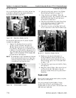
terminal securing nut to avoid twisting the
stud.
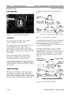
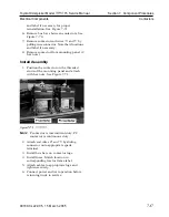
Figure 7-50. View of Steer Motor Commutator
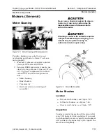
The commutator should be inspected for
surface condition and high mica.
The commutator must be smooth and clean to
provide maximum brush wear. When
commutators are not properly maintained,
carbon dust can collect in the grooves between
the segments. This can lead to
a
short circuit in
the armature.
Good commutation will be indicated by a
dark-brown, polished commutator and an
evenly polished brush wearing surface.
If the commutator appears rough, pitted, or has
signs of burning or heavy arcing between the
commutator bars, the motor should be removed
for servicing.
Terminal Nuts
Whenever you disconnect and reconnect any
power leads to a motor, always tighten the
motor cable securing nuts with a torque wrench
to prevent over-tightening them and damaging
the motor. Use a second wrench on the stud
Motor Cable
Securing Nut
Fiber
Securing
Nut
Figure
7-5 1 .
Motor Terminal Double Nut
Stud terminal securing nuts should be torqued
to 140-160 in. lbs. (15.8-18.1 Nm) and motor
cable securing nuts to 100- 120 in. lbs.
(1
1.2- 13.6 Nm). Check these torques each time
you check motor brushes.
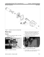
Two different methods are used to connect
power leads on this truck. The double nut
method is shown in Figure 7-5 1. The triple nut
method is shown in Figure 7-52. The torques
listed in the paragraph above apply to both
methods.
Motor Cable
Terminal Stud
Securing Nut
\
Cable Lug
I
Washer
1
o r 2
Stud
Terminal
Housing
Securing
Nut
Figure 7 -5 2 . Motor Terminal Triple Nut
00700-CL222-05, 1
5 March 2005
Summary of Contents for 7BPUE15
Page 1: ...Serial Numbers Service Manual 80 001 and up 7BPUE15...
Page 2: ......
Page 5: ......
Page 58: ......
Page 144: ......
Page 299: ......
Page 301: ......
Page 346: ......
Page 358: ......
Page 386: ...Figure A 6 Cont Elec Schematic Sheet I Part 2 of 2 00700 CL222 05 15 March 2005...
Page 389: ......
Page 391: ...Hydraulic Schematic RES Figure A 9 Hydraulic Schematic 00700 CL222 05 15 March 2005...
Page 400: ......
Page 401: ...Printed in the USA...


