Section
9. Theory of Operation
Toyota Orderpicker Model
15 Service Manual
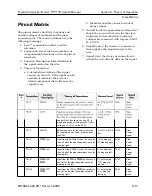
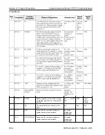
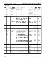
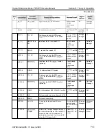
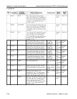
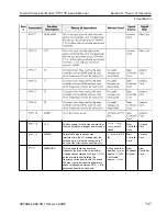
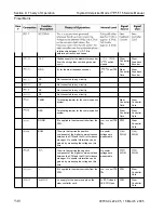
Pinout Matrix
00700-CL222-05, 1
5 March 2005
1
JPC
12VP
STEER
POSITION A
DGND
N C
DGND
BUS+
LED
1
LED 2
LED 3
Supplies working voltage to the Steer
Position Prox when
is present on
the STM.
If
not present, check voltage at
STM
and see
if
is lit.
Output of Home Sensor Prox used by the
ESM
to determine
if
the drive unit is C W
or CCW of center. When over metal
(CW), the switch is closed and the output
is low. When not over metal (CCW), the
switch is open and the output is hi.
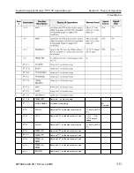
DGND is the B- for the Steer Position Prox
switch. It is connected through the STM.
Not connected to any circuitry on the
STM.
The
B-
for the Steer Controller. It is
connected through the STM.
The wire that carries the positive
component of the digital communications
between the STM and the Wire Guidance
manager. N o usable information can be
gained by measuring the voltage on this
wire.
The wire that carries the negative
component of the digital communications
between the STM and the Wire Guidance
manager. N o usable information can be
gained by measuring the voltage on this
wire.
Takes LED
1
to B- when the C M wants it
turned on.
Takes LED 2 to
B-
when the C M wants it
turned on.
Takes LED 3 to B- when the C M wants it
turned on.
with
switch
closed
Over metal= less
than
Not over metal=
8V.
wrt TP4
(B-)
N A
wrt
TP4
No useful
voltages are
measurable
N o useful
voltages are
measurable
LED
LED
WRT
LED
LED
WRT
LED
LED On=
WRT
STM
Steer
Position
Prox
Steer
Position
Prox
N
A
STM
W G M
W G M
Carriage
Manager
Carriage
Manager
Carriage
Manager
Steer
Position
Prox
Steer
Controller
Card
STM
N
A
Steer
Controller
Card
W G M
W G M
Displa
y
Card
Display
Card
Displa
y
Card
Summary of Contents for 7BPUE15
Page 1: ...Serial Numbers Service Manual 80 001 and up 7BPUE15...
Page 2: ......
Page 5: ......
Page 58: ......
Page 144: ......
Page 299: ......
Page 301: ......
Page 346: ......
Page 358: ......
Page 386: ...Figure A 6 Cont Elec Schematic Sheet I Part 2 of 2 00700 CL222 05 15 March 2005...
Page 389: ......
Page 391: ...Hydraulic Schematic RES Figure A 9 Hydraulic Schematic 00700 CL222 05 15 March 2005...
Page 400: ......
Page 401: ...Printed in the USA...

